-
PRODUCTS & SERVICESOptimized cooling solutions for modern data centersProducts & ServicesOptimized cooling solutions for modern data centers
-
CAPABILITIESAdvancing liquid cooling technologiesCapabilitiesAdvancing liquid cooling technologies
-
TechnologiesLiquid Cooling InnovationTechnologiesLiquid Cooling Innovation
-
RESOURCESLatest News & InformationResourcesLatest News & Information
-
ABOUTOur history, leadership and ownershipAboutOur history, leadership and ownership
-
CONTACTFacility locations and global operational footprint

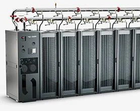
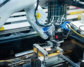




China Best Energy Storage Connector Manufacturers?
As battery projects expand across utility, commercial, and industrial settings, the connector becomes a small component with a major job. It must carry current reliably while handling heat, vibration, dust, and repeated maintenance. An Energy Storage Connector is not selected by appearance alone. Its design affects installation time, system safety, and long-term service needs.
China has a broad supplier base, but “best” depends on the project. Buyers should compare rated voltage and current, contact resistance, temperature-rise data, ingress protection, and mating-cycle performance. Ask for test reports that match the exact product model, not a similar-looking series. Check whether the manufacturer can explain materials, production controls, traceability, and sample testing in clear terms. Useful details matter: cable size, terminal fit, locking feel, and access for service technicians.
This guide will examine how to assess Chinese manufacturers, verify product claims, and match connector designs to different storage applications. It will also consider communication, customization, lead times, and after-sales support. A low quotation can be attractive. It is not enough. Published specifications may not answer every field question, and supplier comparisons are rarely perfect. That uncertainty deserves attention, not a confident guess. Readers can use the criteria ahead to build a practical shortlist and ask more precise questions before requesting samples or placing an order.
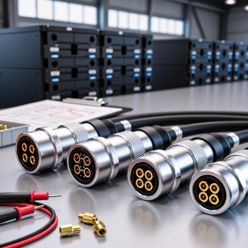
Table of Contents [Hide]
Energy Storage Connectors: Definition, Components, and Types
Energy storage connectors carry power between battery modules, racks, inverters, and service equipment. They also help maintain reliable electrical contact as systems charge and discharge. Unlike ordinary low-voltage plugs, many are designed for substantial current, repeated mating, and demanding installation conditions. Ratings vary, so the connector must match the system rather than merely fit the cable.
A typical assembly includes conductive contacts, an insulating housing, cable termination points, and a locking mechanism. Copper-alloy contacts provide the current path, while plating can help limit corrosion and contact resistance. The housing separates live contacts and may include features that guide insertion or prevent accidental release. Seals, touch-safe barriers, and temperature sensors appear in some designs. Details matter. Yet extra features do not replace correct installation or inspection.
Common types include cable-to-cable connectors, module interconnects, and rack-level power connectors. Some use bolted terminals for fixed, high-current connections; others use quick-connect formats for modular equipment and maintenance. Selection depends on rated voltage and current, conductor size, temperature, vibration, and the number of expected connection cycles. A connector may feel secure but still be poorly matched to its cable or operating environment. Check manufacturer specifications and applicable equipment requirements, then verify the completed connection under the intended conditions.