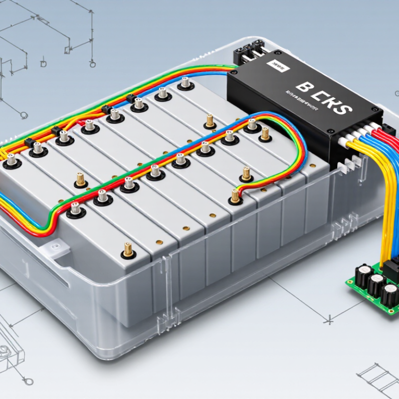
| Core Purpose | Battery-management-system wire harness | Creates an organized electrical connection between battery cells, cell-monitoring circuits, sensors, contactors, and the BMS control unit. | Battery module or pack to the BMS control board | Combines low-voltage measurement, temperature-sensing, communication, and control conductors in one routed assembly. | Conductors must be correctly identified and connected because a wiring error can produce inaccurate measurements or damage monitoring electronics. |
| Cell Voltage Measurement | Cell-tap wires | Carry the voltage of individual cells or groups of cells to the cell-monitoring circuit. | Cell interconnects, busbars, or module terminals to cell-monitoring inputs | Multiple sense wires are arranged in an ordered sequence; adjacent conductors may differ by the voltage of one cell group. | Correct wire order, secure terminals, insulation, and adequate creepage and clearance are essential. |
| Voltage Reference | Reference or negative-potential lead | Provides the electrical reference used to interpret the cell-voltage measurement chain. | Battery negative or the designated module reference point to the monitoring circuit | Often forms the starting point of the cell-tap sequence. | The reference lead should be clearly identified and protected against accidental reversal or short circuit. |
| Temperature Monitoring | Thermistor or temperature-sensor wires | Transmit temperature readings from cells, busbars, or thermal interfaces to the BMS. | Temperature sensors located between or near cells to the BMS measurement inputs | Usually low-current sensor circuits; resistance changes with temperature when thermistors are used. | Sensors should maintain firm thermal contact without damaging cell insulation or creating pressure points. |
| Current Measurement | Current-sensor signal wires | Send measured current information to the BMS so it can estimate state of charge and detect overcurrent conditions. | Shunt, Hall-effect sensor, or other current-sensing device to the BMS | May include differential signal, supply, ground, or digital communication conductors depending on the sensor design. | Signal conductors should be routed away from high-current switching paths where practical to reduce electrical noise. |
| Contactor Control | Contactor coil and precharge-control wires | Allow the BMS to control the connection of the battery pack to the external load and charger. | BMS control circuitry to positive, negative, and precharge contactors | Control circuits are separate from the high-current power path; coil voltage and current must match the contactor requirements. | Precharge control helps limit inrush current into capacitive loads. Interlocks and fail-safe logic are commonly used. |
| Communication | Communication-pair wiring | Transfers measurement data, diagnostic information, commands, and status between BMS modules and a higher-level controller. | Cell-monitoring unit, master BMS, vehicle controller, charger, or energy-management system | Common interfaces include differential communication buses; twisted-pair construction is often used to improve noise immunity. | Maintain correct polarity, termination, shielding requirements, and cable routing specified by the communication system. |
| Low-Voltage Power | Auxiliary supply and ground wires | Provide operating power and return paths for monitoring boards, sensors, relays, and communication circuits. | Low-voltage battery or isolated power supply to BMS electronics | Wire size is selected according to continuous current, voltage drop, temperature, and allowable insulation temperature. | Protection against reverse polarity, short circuits, and overvoltage is required at the system level. |
| Service and Safety | Interlock and service-disconnect wiring | Indicates whether covers, connectors, service plugs, and other safety components are correctly closed or installed. | Service disconnect, enclosure interlock, connector lock, or emergency shutdown loop to the BMS | Often operates as a continuity loop that changes state when a safety device is opened. | The circuit should be designed so that a broken wire or open connector produces a safe fault condition. |
| Connector System | Multi-pin harness connectors and terminals | Provide detachable, keyed, and protected interfaces between the harness and battery-management components. | Cell-monitoring board, BMS controller, sensor, contactor, or module interface | May include locking features, polarization, terminal seals, strain relief, and touch-safe housings. | Connector ratings must cover voltage, current, temperature, vibration, environmental exposure, and mating-cycle requirements. |
| Mechanical Protection | Insulation, conduit, tape, clips, and protective sleeving | Protect conductors from abrasion, vibration, heat, moisture, and contact with conductive battery structures. | Along module edges, enclosure walls, busbar areas, and connector exits | Materials are selected for flexibility, temperature range, flame behavior, chemical resistance, and insulation performance. | Harnesses should be secured without excessive bending, crushing, tension, or interference with cell expansion and service access. |
| Signal Integrity | Separated and routed measurement circuits | Helps preserve accurate low-level voltage, temperature, and communication signals in the presence of switching and high-current conductors. | Between sensors, monitoring boards, contactors, and the central BMS | Twisted pairs, short signal paths, shielding, filtering, and physical separation may be applied where required. | Routing should minimize large loop areas and avoid parallel runs beside noisy power cables when possible. |
| Electrical Isolation | Isolation barriers and isolated signal interfaces | Reduce the risk of hazardous voltage reaching low-voltage control electronics or communication equipment. | Between high-voltage battery circuits and low-voltage control domains | Isolation may be provided by isolated power supplies, isolated transceivers, sensors, or contactor interfaces. | Required isolation voltage, creepage, clearance, and insulation system depend on the pack voltage and applicable safety standard. |
| Wire Identification | Labels, colors, numbering, and circuit documentation | Supports correct assembly, inspection, troubleshooting, and service replacement. | At connectors, branch points, terminals, and both ends of individual circuits | Identification normally corresponds to a wiring diagram, pinout, terminal number, or circuit designation. | Markings should remain legible after exposure to heat, vibration, fluids, and routine maintenance. |
| Testing and Validation | Harness inspection and electrical test points | Confirms continuity, insulation integrity, correct pin mapping, polarity, sensor response, and absence of unintended shorts. | Production test fixture, connector interfaces, cell-tap points, and sensor terminals | Typical checks include visual inspection, continuity testing, resistance measurement, insulation testing, and functional verification. | Testing must follow the battery and BMS manufacturer’s approved procedure to avoid applying an unsuitable test voltage to electronics. |
| Operational Outcome | Complete integrated harness assembly | Enables the BMS to monitor cell voltage and temperature, estimate battery condition, control switching devices, and report faults. | Throughout the battery module or complete battery pack | Performance depends on accurate wiring, stable connections, suitable protection, and correct BMS configuration. | A harness does not independently balance or protect cells; it provides the electrical pathways required for the BMS to perform those functions. |