-
PRODUCTS & SERVICESOptimized cooling solutions for modern data centersProducts & ServicesOptimized cooling solutions for modern data centers
-
CAPABILITIESAdvancing liquid cooling technologiesCapabilitiesAdvancing liquid cooling technologies
-
TechnologiesLiquid Cooling InnovationTechnologiesLiquid Cooling Innovation
-
RESOURCESLatest News & InformationResourcesLatest News & Information
-
ABOUTOur history, leadership and ownershipAboutOur history, leadership and ownership
-
CONTACTFacility locations and global operational footprint





Why Are Branch Circuit Breakers Essential for Safety?
Why Are Branch Circuit Breakers Essential for Safety?
Every powered outlet hides a potential fault. A damaged cord, loose terminal, or overloaded receptacle can generate heat inside a wall. Branch Circuit Breakers interrupt that dangerous current before conductors reach failure temperatures. Their role is simple, but not minor. They protect individual circuits, connected equipment, and people working near energized systems.
The National Fire Protection Association reported an annual average of 35,150 U.S. home structure fires involving electrical distribution and lighting equipment from 2012 to 2016. These fires caused approximately 470 civilian deaths, 1,100 injuries, and $1.3 billion in direct property damage. Those figures explain why circuit protection cannot be treated as a box-checking exercise. NFPA 70, the National Electrical Code, also establishes requirements for branch-circuit conductors, overcurrent protection, and installation practices. Licensed professionals use these requirements with load calculations and inspection experience.
A breaker reacts to abnormal current. It does not repair damaged insulation or replace proper maintenance. That distinction matters. A correctly sized breaker should trip during a short circuit or sustained overload, limiting energy before wiring overheats. The U.S. Consumer Product Safety Commission has repeatedly warned about overloaded circuits, damaged electrical products, and fire risks in homes. Yet safety assumptions can still fail. A breaker may appear functional while connections loosen behind a panel. Regular inspection, torque verification, and appropriate replacement remain essential. No device is magic. Reliable protection comes from sound design, qualified installation, and careful attention to changing loads.
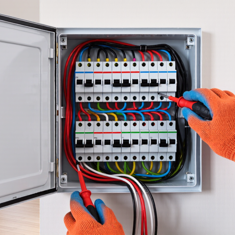
Table of Contents [Hide]
What Is a Branch Circuit Breaker and How Does It Work?
A branch circuit breaker controls power flowing through one household circuit. It protects wiring that supplies outlets, lights, or fixed appliances. Inside the electrical panel, the breaker monitors current continuously. When current rises above its safe rating, it opens the circuit. Power stops flowing.
Most breakers use thermal and magnetic protection. A thermal element reacts to a sustained overload and trips after heating. A magnetic mechanism responds almost instantly to a short circuit. This timing helps separate ordinary overloads from sudden, dangerous faults. The breaker must match the circuit wiring and expected load. A higher rating is not automatically safer.
During electrical inspections, repeated tripping is a common warning sign. It may indicate damaged insulation, excessive appliances, or a failing device. Resetting the breaker again is not repair. That habit deserves reflection. For example, a circuit carrying a heater, kettle, and microwave may overload during normal use. An electrician should measure the load and inspect connections before changing equipment.
Some branch breakers also detect leakage or arc faults, depending on their design. These features can reduce risks in damp areas or older wiring systems. However, no breaker replaces sound installation, proper grounding, or careful maintenance. Warm covers, buzzing sounds, burning smells, or discoloration need prompt attention. Keep the panel dry and accessible. Only a qualified professional should open it or alter circuit protection.