-
PRODUCTS & SERVICESOptimized cooling solutions for modern data centersProducts & ServicesOptimized cooling solutions for modern data centers
-
CAPABILITIESAdvancing liquid cooling technologiesCapabilitiesAdvancing liquid cooling technologies
-
TechnologiesLiquid Cooling InnovationTechnologiesLiquid Cooling Innovation
-
RESOURCESLatest News & InformationResourcesLatest News & Information
-
ABOUTOur history, leadership and ownershipAboutOur history, leadership and ownership
-
CONTACTFacility locations and global operational footprint







How to Choose a Centrifugal Vent Fan in 2026?
Choosing a Centrifugal Vent Fan in 2026 requires more than comparing airflow and purchase prices. The fan must match the building’s pressure, duty cycle, noise limits, and maintenance conditions. A kitchen exhaust system faces grease and heat. A workshop system may handle dust, moisture, or corrosive vapors. These differences quickly change the correct selection.
Energy performance deserves close attention. The International Energy Agency reports that buildings used about 30% of global final energy in 2022 and produced approximately 26% of energy-related emissions. A poorly selected fan can increase pressure losses, motor demand, and operating costs for years. The U.S. Department of Energy also identifies fan systems as important targets for industrial efficiency improvements. Variable-speed control, efficient motors, clean filters, and correctly sized ducts can reduce unnecessary electricity use. Small details matter.
Standards provide a safer starting point. ASHRAE Standard 62.1 helps define acceptable ventilation requirements for many commercial spaces. AMCA 210 provides recognized methods for testing fan airflow and pressure performance. These documents improve comparison quality, but they do not replace site measurements. Real installations rarely behave perfectly. A catalogue rating may not reflect a long duct run, a clogged filter, or an awkward discharge elbow. That is where experience matters.
The best 2026 choice balances verified performance, lifecycle cost, acoustic comfort, service access, and application risk. Buyers should request certified test data, motor details, control compatibility, and a clear performance curve. There is no universal winner. A quieter fan may cost more. A cheaper unit may consume more power. The final decision should remain evidence-based, practical, and open to revision after commissioning.
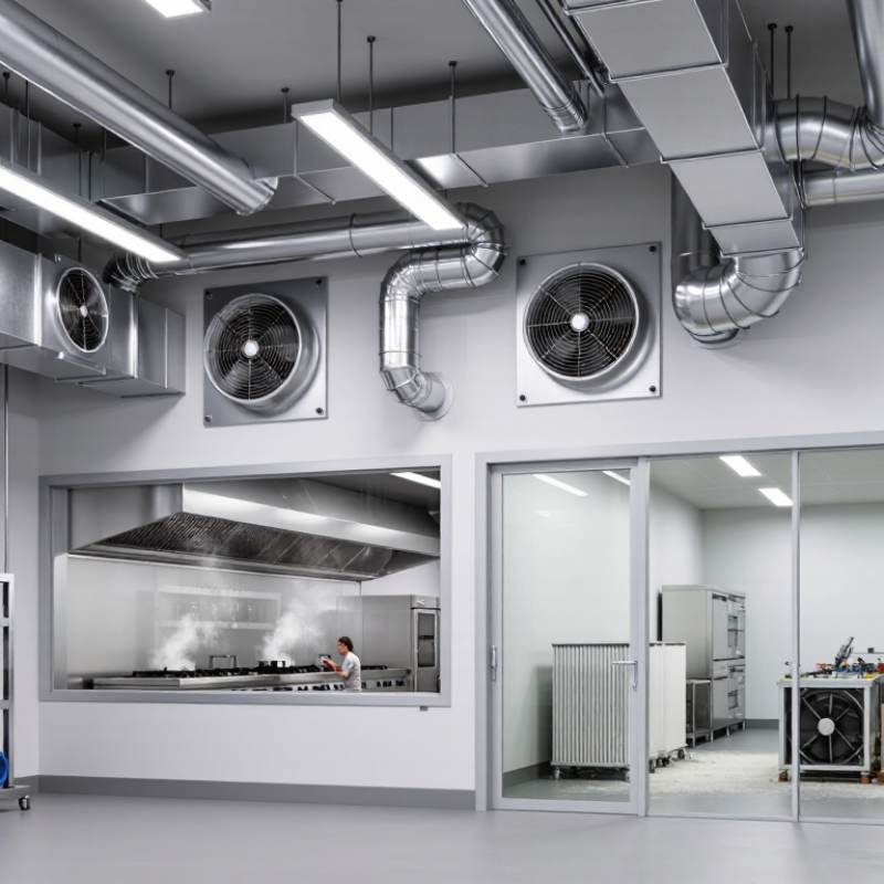
Table of Contents [Hide]
What Is a Centrifugal Vent Fan and How Does It Work?
A centrifugal vent fan moves air by changing its direction through a rotating impeller. Air enters near the center, then travels outward across curved blades. The blades add energy and pressure. A surrounding housing guides the air into the discharge duct.
This design differs from an axial fan. An axial fan pushes air straight through, like a propeller. A centrifugal fan works better against duct resistance, bends, filters, and grilles. That makes it useful in bathrooms, workshops, kitchens, and commercial spaces. The motor turns the impeller. The housing reduces turbulence and helps maintain steady airflow.
In 2026, choosing one should begin with real operating conditions. Measure the duct length, count sharp bends, and check the required airflow. A fan with a large airflow rating may perform poorly in a restrictive system. I have seen installations where the advertised airflow looked impressive, but weak duct planning caused noisy, disappointing results.
Static pressure matters. So does sound. A kitchen fan may need stronger pressure, while a bedroom requires quieter operation. Check the fan curve rather than trusting one airflow number. Energy use, maintenance access, and moisture resistance also deserve attention. A clean impeller usually performs better. It is easy to overlook.
One practical mistake is selecting by duct diameter alone. The room size, air leakage, and daily use pattern also affect performance. Specifications can be imperfect, and field conditions often differ. Recheck the calculation before installation.