-
PRODUCTS & SERVICESOptimized cooling solutions for modern data centersProducts & ServicesOptimized cooling solutions for modern data centers
-
CAPABILITIESAdvancing liquid cooling technologiesCapabilitiesAdvancing liquid cooling technologies
-
TechnologiesLiquid Cooling InnovationTechnologiesLiquid Cooling Innovation
-
RESOURCESLatest News & InformationResourcesLatest News & Information
-
ABOUTOur history, leadership and ownershipAboutOur history, leadership and ownership
-
CONTACTFacility locations and global operational footprint







How to Choose an ANSI Rated Three Phase Oil Transformer?
Choosing an Ansi Rated Three Phase Oil Transformer For Utility Use requires more than comparing voltage, capacity, and price. Utility networks face changing loads, weather exposure, switching events, and long maintenance intervals. A transformer that looks suitable on paper may perform poorly beside a dusty substation fence. The decision must connect electrical design with real operating conditions.
John J. Winders Jr., a respected transformer engineering author, offers a useful reminder: “Transformer reliability depends on proper application, installation, and maintenance.” His point is practical. The ANSI rating supports recognized performance expectations, but it does not replace site engineering. Buyers should verify primary and secondary voltages, frequency, impedance, cooling class, insulation levels, sound limits, and expected fault duty. They should also review oil containment, bushings, tap arrangements, and accessory quality.
Field experience matters here. Ask how the unit behaved during summer peaks, cold starts, and repeated feeder switching. Request test records, factory inspection details, and clear warranty terms. Check whether replacement parts remain available after installation. This step is often overlooked.
There is no perfect transformer. A slightly oversized unit may improve future capacity, yet it can increase cost and reduce efficiency during light loading. A compact design may fit the site, but leave little room for expansion. That tradeoff deserves honest review. The strongest choice balances safety, efficiency, serviceability, and lifecycle cost. It should also match the utility’s maintenance culture, not just its procurement spreadsheet.
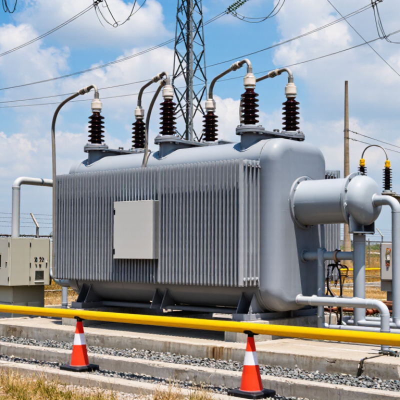
Table of Contents [Hide]
Understanding ANSI Ratings for Three-Phase Oil Transformers
How to Choose an ANSI Rated Three Phase Oil Transformer?
Understanding ANSI Ratings for Three-Phase Oil Transformers
An ANSI rating is not a single performance score. It indicates compliance with applicable ANSI/IEEE C57 standards for design, construction, and testing. These standards address insulation strength, temperature rise, short-circuit capability, sound levels, and dielectric performance. A transformer can meet ANSI requirements yet still be unsuitable for a specific installation. Do not guess.
Start with the electrical duty. Confirm the primary and secondary voltages, kVA capacity, frequency, impedance, tap range, and phase configuration. Load growth matters too. An undersized transformer may run hot, while excessive capacity can increase cost and losses. Field experience shows that nameplate details deserve careful review. A small voltage mismatch can create major operating problems.
Check the installation environment before comparing quotations. Record the ambient temperature, altitude, indoor or outdoor location, available fault current, and required cooling method. Ask for the certified factory test report, routine test results, oil specifications, and applicable ANSI/IEEE references. Inspect the tank, bushings, gauges, and grounding points when the unit arrives. Shipping damage is easy to overlook. It should not be. I also recheck protection coordination after energization, because calculated settings may not reflect actual system behavior. The standard provides a reliable baseline, but site conditions still require engineering judgment.