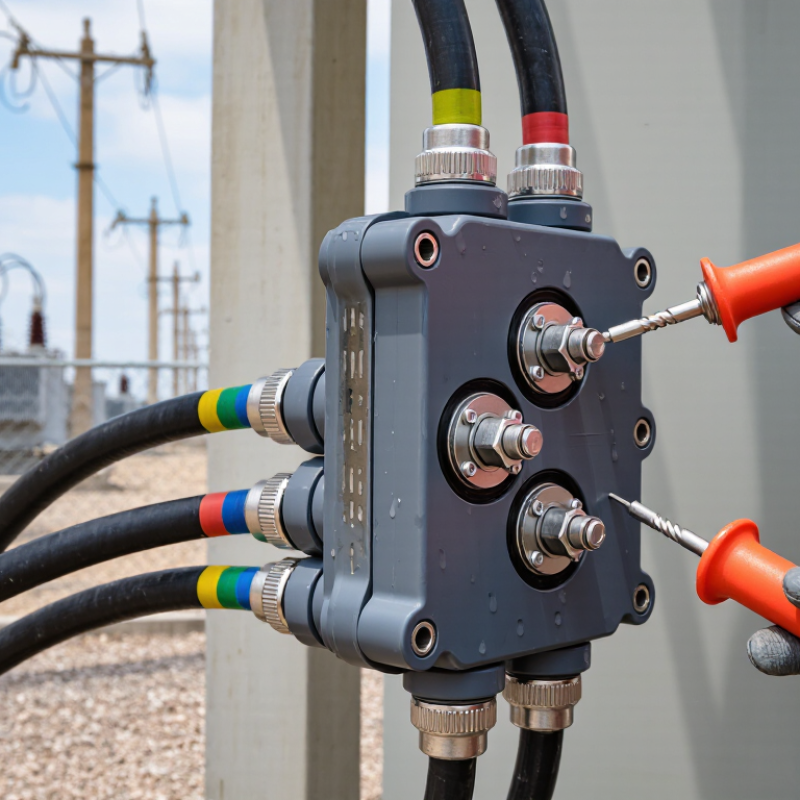
| 1. Electrical Rating and System Compatibility |
| Equipment class | 15 kV class | Suitable for medium-voltage systems up to approximately 15 kV line-to-line, commonly including 8.3/14.4 kV grounded-wye systems. | Confirm the system voltage, phase-to-ground voltage, grounding method, and the applicable utility or project specification. |
| Continuous current | 200 A | The complete junction assembly, bushing interface, connector, and cable must each be rated for at least 200 A continuous current. | Do not select a component solely because the cable ampacity exceeds 200 A; the separable interface rating must also be 200 A. |
| Insulation level | 95 kV BIL typical | A 15 kV class loadbreak interface commonly uses a 95 kV basic impulse insulation level. Switching and power-frequency withstand values must match the approved design. | Check the certified BIL, AC withstand, partial-discharge, and temperature ratings for the complete mating assembly. |
| Frequency | 50 or 60 Hz | Most 15 kV distribution applications operate at 50 Hz or 60 Hz, but the frequency must be compatible with the system and test documentation. | Verify frequency when the junction is used in an imported, industrial, or special-purpose distribution system. |
| 2. Interface Type and Mating Components |
| Primary interface | 200 A loadbreak separable interface | Use a junction designed for a standardized 200 A loadbreak bushing well, parking stand, feed-through insert, or equivalent mating component. | Confirm that the junction, bushing well, connector body, probe, and insulating cap belong to the same interface family and voltage class. |
| Loadbreak operation | Loadbreak-rated only | The connection may be operated under the manufacturer's specified loadbreak conditions using the correct operating tool and procedure. | Confirm whether the assembly is approved for load interruption, energized installation, dead-front operation, or only de-energized maintenance. |
| Fault-duty capability | System fault current dependent | Short-circuit withstand and fault-closing capability are separate from the 200 A continuous-current rating and must be adequate for the available fault current. | Compare the certified short-time and fault-closing ratings with the calculated system fault current and clearing time. |
| Mating geometry | Same dimensional interface | Key dimensions include contact-probe geometry, interface diameter, elbow seating depth, parking position, and insulating-cap fit. | Use dimensional drawings rather than nominal voltage or current labels alone; incompatible interfaces may not fully engage or seal. |
| 3. Cable Size and Insulation Diameter |
| Common cable conductor sizes | 1/0 AWG to 4/0 AWG typical | These conductor sizes are frequently encountered in 15 kV, 200 A distribution applications, but the correct size depends on ampacity, voltage drop, installation method, and fault duty. | Confirm conductor material, compact or compressed construction, strand count, shielding arrangement, and actual cable manufacturer's dimensions. |
| Typical insulation diameter band | Approximately 16–38 mm (0.63–1.50 in) | This is a practical screening range for many 15 kV shielded cables used with 200 A separable connectors. It is not a universal connector acceptance range. | Measure or obtain the actual diameter over the semiconductive insulation shield. Select a connector whose specified insulation-diameter range includes that value. |
| Example cable selection bands | Use only as an initial check | 1/0 AWG: approximately 16–28 mm insulation diameter 2/0 AWG: approximately 18–31 mm insulation diameter 4/0 AWG: approximately 22–38 mm insulation diameter | Actual dimensions vary with conductor compactness, insulation thickness, metallic shield, water-blocking layer, and jacket construction. Always use the cable data sheet for final selection. |
| Insulation thickness | 100% or 133% insulation level | 15 kV cables may use different insulation levels, commonly identified as 100% or 133%. The insulation thickness affects the cable diameter and stress-control fit. | Match the connector stress-control components to the actual cable insulation diameter, not just the conductor gauge. |
| Cable preparation | Manufacturer-defined strip dimensions | Critical preparation dimensions include jacket removal, shield cutback, semiconductive-screen removal, insulation length, and conductor exposure. | Use the approved preparation tool and dimensional chart. An incorrect screen cutback can cause electrical stress concentration or sealing failure. |
| 4. Grounding and Shielding Design |
| Cable shield type | Concentric neutral, copper tape, wire shield, or drain wire | The junction must provide a practical termination path for the cable metallic shield and maintain the intended grounding and bonding arrangement. | Identify the shield construction before ordering. Shield accessories and grounding leads are not interchangeable across cable designs. |
| Grounding lead | Separate grounding connection required | A flexible copper ground lead is commonly connected from the cable shield or concentric neutral to the system grounding point or equipment ground bar. | Verify conductor size, insulation type, connection hardware, routing, and the required minimum fault-current withstand. |
| Shield bonding method | Single-point or both-end bonding | Single-point bonding can reduce circulating shield current, while both-end bonding provides a low-impedance fault-current path. The correct method depends on the system design. | Follow the protection and grounding study. Do not change shield-bonding practice solely to simplify junction installation. |
| Grounding hardware | Corrosion-resistant, mechanically secure connections | Ground lugs, compression connectors, bonding clamps, and fasteners must be compatible with the shield material and the installation environment. | Check torque values, crimp tooling, conductor compatibility, corrosion protection, and accessibility for inspection. |
| Grounding continuity | Required before energization | The metallic shield, grounding lead, junction enclosure or bracket, and equipment grounding system should have verified electrical continuity. | Perform the required continuity and bonding tests, then document the results according to the project commissioning procedure. |
| 5. Environmental and Installation Conditions |
| Installation location | Indoor, outdoor, vault, or pad-mounted | Outdoor and below-grade applications require suitable sealing, UV resistance, pollution performance, water resistance, and mechanical protection. | Confirm enclosure rating, operating temperature, altitude, humidity, flooding exposure, salt contamination, and chemical exposure. |
| Cable bending radius | Per cable manufacturer's limit | The junction layout must allow the cable to enter without exceeding the minimum bending radius, especially near the connector stress-control area. | Check the cable's installation and final minimum bending-radius values and allow additional space for maintenance and testing. |
| Touch-safe construction | Dead-front design preferred | Insulated, shielded separable connectors reduce exposure to energized conductors when correctly installed with the required caps and accessories. | Confirm touch-safe requirements, exposed conductive parts, grounding provisions, and the approved operating procedure. |
| 6. Final Selection Checklist |
| Recommended selection sequence | Interface first, cable second, grounding third | 1. Confirm the 15 kV class and 200 A rating. 2. Match the 200 A loadbreak interface and mating components. 3. Confirm the cable conductor size and actual insulation diameter. 4. Select the correct stress-control and sealing components. 5. Define shield bonding and grounding accessories. 6. Verify environmental, fault-duty, and installation requirements. | All dimensions and ratings must be verified against approved technical drawings |
| Important engineering note | Nominal values such as “15 kV” and “200 A” do not guarantee compatibility. Final selection must be based on the actual bushing interface, certified electrical ratings, cable insulation diameter, cable preparation dimensions, shield construction, grounding design, and installation conditions. |