-
PRODUCTS & SERVICESOptimized cooling solutions for modern data centersProducts & ServicesOptimized cooling solutions for modern data centers
-
CAPABILITIESAdvancing liquid cooling technologiesCapabilitiesAdvancing liquid cooling technologies
-
TechnologiesLiquid Cooling InnovationTechnologiesLiquid Cooling Innovation
-
RESOURCESLatest News & InformationResourcesLatest News & Information
-
ABOUTOur history, leadership and ownershipAboutOur history, leadership and ownership
-
CONTACTFacility locations and global operational footprint







How to Choose the Right Oil Cooler for CAT in 2026?
Choosing the right Oil Cooler Cat in 2026 requires more than matching a part number. Excavators, wheel loaders, and generators operate under different loads, temperatures, and space limits. A cooler that performs well on a mining site may struggle on a compact loader.
Michael Bremer, a heavy-equipment thermal systems consultant, explains, “A cooler is effective only when its flow, mounting, and operating conditions work together.” That principle shapes this guide. We will examine core materials, oil-flow capacity, pressure ratings, fan performance, hydraulic compatibility, and installation space. Small details matter. A clogged fin can raise oil temperature quickly. Poor airflow can do the same.
Real machines are rarely perfect.
Before choosing an Oil Cooler Cat, inspect the engine model, serial number, working environment, and existing cooling circuit. Record oil temperature during demanding cycles. Check whether mud, dust, or chaff blocks the fins. Also consider vibration, hose routing, and future maintenance access. These practical checks often reveal problems that product brochures overlook.
Some recommendations may need revision after field testing. That is normal. A cooler rated for high capacity may still be unsuitable if its pressure drop is excessive. Likewise, a compact unit may fit neatly but fail during long, hot shifts. This article compares the main selection factors for 2026, helping buyers balance durability, thermal performance, installation accuracy, and total operating cost. The goal is not the largest cooler. It is the most dependable match for the machine and its actual workload.
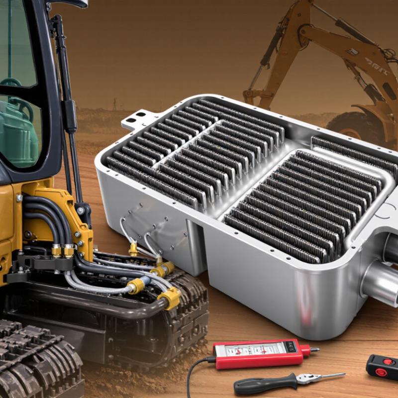
Table of Contents [Hide]
Define Your CAT Machine’s Oil Cooling Requirements
Before choosing an oil cooler, define how your machine actually works. Record engine load, oil temperature, ambient heat, and operating hours. A loader moving soil uphill needs more cooling capacity than one used for light yard work. Measure temperature after continuous operation, not immediately after startup. Short tests can mislead.
Identify the oil circuit carefully. Engine oil, hydraulic oil, and transmission oil may require different cooler designs. Check the manufacturer’s service data for normal operating temperature, maximum pressure, oil flow, and acceptable pressure drop. A cooler that removes excessive heat but restricts flow can still damage the system. It must fit the available space without blocking airflow or routine filter access.
Dust, mud, vibration, and debris also shape the requirement. In a quarry, a compact stacked-plate cooler may need strong guards and easy cleaning access. In hot climates, add capacity for high ambient temperatures and slow machine speeds. Use temperature sensors before and after the cooler when possible. Compare readings across several work cycles. One mistake is selecting by engine size alone; real heat rejection depends on duty cycle, oil condition, airflow, and maintenance. I would also leave a modest capacity margin, but not guess blindly. Oversizing can increase cost, weight, and installation complexity.
How to Choose the Right Oil Cooler for CAT in 2026? - Define Your CAT Machine’s Oil Cooling Requirements
| Requirement | What to Measure | Typical Planning Range | Why It Matters | Selection Guidance |
|---|---|---|---|---|
| Machine duty | Machine type, engine output, operating hours, ambient temperature and workload | Light, moderate or severe continuous duty | A cooler sized for intermittent work may overheat during continuous loading | Use the highest expected duty cycle and ambient temperature, not the average operating condition |
| Engine power class | Rated engine power in kW or hp | Approximately 50–100 kW, 100–200 kW, or above 200 kW | Higher power generally produces greater heat rejection and oil circulation demand | Treat power class as a preliminary guide; final sizing must use measured or manufacturer-specified oil data |
| Oil flow rate | Maximum oil flow through the cooler in L/min | Common hydraulic and engine-oil cooler circuits may range from approximately 20–200 L/min | Insufficient flow capacity can cause excessive pressure drop and inadequate cooling | Select a cooler rated above the maximum actual flow, while checking the complete system curve |
| Required heat rejection | Heat load in kW, calculated from oil flow, oil density, specific heat and temperature change | Often estimated at roughly 5–15% of engine power for an initial assessment, subject to system design | A cooler can have adequate flow capacity but still reject too little heat | Use certified performance data at the actual oil flow, air or coolant temperature, and inlet temperature |
| Oil inlet temperature | Maximum oil temperature entering the cooler | Many heavy-duty oil circuits are designed around approximately 90–120°C; verify the oil specification | Temperature affects viscosity, seal life, oxidation rate and cooler capacity | Base the selection on the maximum steady-state temperature and short-duration peak temperature |
| Cooling-medium temperature | Ambient air temperature for air-cooled units or coolant temperature for liquid-cooled units | Typical design ambient conditions may range from 35–50°C in demanding applications | Higher cooling-medium temperature reduces the available temperature difference | Use the hottest site condition and account for airflow recirculation around the radiator compartment |
| Permitted pressure drop | Pressure loss across the oil side at maximum flow | Confirm the circuit limit; many systems target approximately 0.3–1.5 bar depending on location and oil viscosity | Excessive pressure loss can reduce lubrication flow or trigger bypass operation | Check cold-start pressure drop as well as hot-oil pressure drop because cold oil is more viscous |
| Oil viscosity and fluid type | Oil grade, viscosity range, additives and compatibility requirements | Common heavy-duty lubricants include multigrade engine and hydraulic oils; actual viscosity varies with temperature | Viscosity directly affects pressure drop, heat transfer and startup performance | Use performance curves tested with a fluid of comparable viscosity, density and thermal properties |
| Cooler configuration | Air-to-oil or liquid-to-oil design, fan arrangement, mounting orientation and available space | Air-cooled units suit independent airflow; liquid-cooled units suit compact integrated layouts | The configuration determines heat-transfer performance, packaging and maintenance access | Choose air cooling where airflow is reliable; choose liquid cooling where compactness and controlled coolant temperature are priorities |
| Installation envelope | Maximum length, width, height, weight, hose routing and service clearance | Allow sufficient clearance for airflow, cleaning, vibration isolation and connection access | A correctly rated cooler may underperform if airflow is blocked or maintenance is impossible | Reserve access for fin cleaning, filter service, hose replacement and inspection |
| Connection details | Port size, thread or flange type, port orientation and hose inside diameter | Common connection sizes vary with flow; do not size ports by outside diameter alone | Incorrect connections can create leaks, restriction, vibration damage or installation delays | Match the existing circuit standard and verify sealing method, torque and hose bend radius |
| Environmental resistance | Dust, mud, salt, moisture, vibration, shock and corrosive exposure | Off-road equipment commonly requires reinforced construction and corrosion-resistant surface protection | Contaminated fins and vibration fatigue can reduce cooling capacity and service life | Consider bar-and-plate construction, protective coatings, fin spacing and vibration-resistant mounting |
| Safety and validation | Pressure rating, burst pressure, leak test, temperature rating and bypass requirements | The cooler should be rated above the maximum operating pressure and temperature of the circuit | Validation reduces the risk of leakage, thermal failure and unplanned downtime | Review test certificates, performance curves and the complete system operating envelope before installation |
Note: The numerical ranges are preliminary engineering references for selection planning. Final oil-cooler sizing must be verified against the machine’s actual oil flow, pressure limits, fluid properties, heat load, operating temperature and installation conditions.