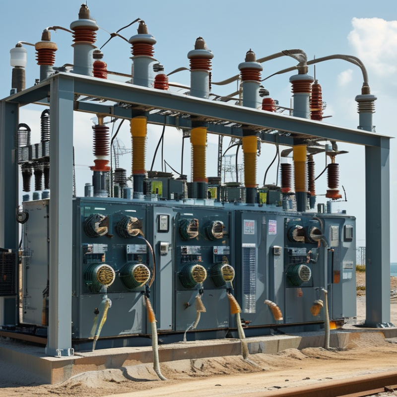
| Substation Bus Configuration | Single Bus | One common bus connects incoming lines, transformer feeders, and outgoing circuits. | Lowest initial cost; simple protection, operation, and expansion. | A bus fault or planned bus maintenance can interrupt all connected circuits unless sectionalizing is added. | Small industrial facilities, distribution substations, and installations where moderate availability is acceptable. |
| Single Bus with Bus Sectionalizer | A circuit breaker or bus-tie device divides the bus into two or more sections. | Improves operational flexibility and limits the affected area during a bus fault. | Better continuity than a basic single-bus arrangement; supports load transfer and staged expansion. | Requires additional switching, protection coordination, and operating procedures. | Medium-size substations with separated loads or multiple transformer feeders. |
| Main-and-Transfer Bus | A transfer bus and bypass arrangement can temporarily replace a feeder breaker during maintenance. | Provides maintenance flexibility while retaining a relatively compact layout. | Allows selected breaker maintenance without a complete feeder outage. | Switching is more complex, and protection settings must support transfer and bypass conditions. | Critical distribution and industrial substations with scheduled maintenance requirements. |
| Double Bus or Double-Breaker Arrangement | Circuits can be connected to two buses or protected by two breakers, depending on the selected scheme. | High operating flexibility and improved availability for important circuits. | Supports maintenance and fault isolation with fewer planned interruptions. | High capital cost, larger footprint, more equipment, and more demanding protection logic. | Transmission substations, major grid nodes, and loads with stringent availability requirements. |
| Transformer Construction | Oil-Immersed Transformer | Active parts are immersed in mineral oil or another approved insulating liquid for insulation and heat transfer. | Efficient cooling, strong overload capability, and broad availability across medium- and high-voltage ratings. | Requires liquid containment, fire-risk assessment, leak prevention, and periodic liquid condition monitoring. | Outdoor substations, utility networks, industrial plants, and high-capacity applications. |
| Dry-Type Transformer | Windings use solid insulation and air-based or forced-air cooling without an insulating liquid. | No liquid leakage; suitable for indoor installation and locations with strict fire or environmental restrictions. | May require more space or ventilation for equivalent capacity; temperature and dust control are important. | Indoor commercial buildings, data facilities, hospitals, tunnels, and compact industrial installations. |
| Two-Winding Transformer | One primary winding and one secondary winding provide galvanic isolation and voltage transformation. | Simple, reliable, and widely used for transmission-to-distribution voltage conversion. | Requires separate equipment for additional voltage levels or independent secondary supplies. | Most general-purpose substations with one high-voltage side and one low- or medium-voltage side. |
| Three-Winding Transformer | One transformer includes high-voltage, medium-voltage, and low-voltage windings. | Can supply two secondary voltage levels while reducing the number of separate transformers. | More complex impedance, fault-current, insulation, and protection calculations; one transformer can be a single point of failure. | Substations serving multiple voltage levels or auxiliary and distribution systems from one site. |
| Voltage Regulation | Fixed Tap Transformer | Voltage taps are changed only when the transformer is de-energized. | Lower cost, simple construction, and limited maintenance requirements. | Cannot correct voltage variations during operation; tap changes require an outage and safety procedure. | Stable utility supplies and installations with limited daily voltage variation. |
| Off-Circuit Tap Changer | Provides several de-energized tap positions, commonly used for commissioning or seasonal adjustment. | Balances cost and flexibility for systems with predictable voltage conditions. | Tap position cannot be changed under load; an outage is required for adjustment. | Distribution substations where voltage correction is occasional rather than continuous. |
| On-Load Tap Changer | Changes transformer turns ratio while energized and carrying load, typically through an automatic voltage-control system. | Maintains voltage within a defined operating band despite load or supply changes. | Improves power-quality control and reduces the need for manual voltage adjustments. | Higher cost and maintenance; switching duty, control settings, and coordination require careful engineering. | Transmission and distribution substations with variable load, long feeders, or renewable generation. |
| Voltage-Regulating Transformer | A dedicated regulating transformer or booster arrangement adjusts voltage independently of the main transformation function. | Provides targeted control on selected lines or load areas. | Useful when voltage control is needed on a specific feeder or interconnection. | Adds equipment, losses, footprint, and control complexity. | Long distribution feeders, interconnected networks, and systems with local voltage constraints. |
| Cooling Method | Natural Oil and Natural Air Cooling | Oil circulates naturally inside the tank and heat dissipates through natural air movement over radiators. | Simple, quiet, and dependable with relatively low auxiliary power consumption. | Cooling capacity depends on ambient conditions and radiator surface area. | Many outdoor distribution and medium-capacity power transformers. |
| Forced-Air-Assisted Cooling | Fans increase air flow across radiators to raise the transformer’s permissible loading. | Higher capacity from the same transformer tank and improved short-term loading capability. | Fans add noise, maintenance requirements, auxiliary power demand, and failure modes. | Large distribution and power transformers where occasional or continuous higher loading is required. |
| Forced-Oil and Forced-Air Cooling | Pumps circulate insulating liquid through coolers, while fans remove heat from the cooler surfaces. | Supports high ratings and effective heat removal in large transformers. | More compact than purely natural cooling for the same rating. | Higher complexity; pumps, fans, controls, and backup arrangements must be maintained and tested. | High-capacity transmission and generation step-up substations. |
| Air-Forced Dry-Type Cooling | Fans direct air across the windings or enclosure to increase the dry-type transformer rating. | Provides additional capacity without using insulating liquid. | Suitable for installations with fire or spill restrictions. | Requires clean airflow, ventilation, fan monitoring, and appropriate acoustic control. | Indoor substations with variable loading and strict environmental requirements. |
| Transformer Rating Selection | Apparent Power Rating | Specified in volt-amperes, commonly kVA or MVA; for a three-phase transformer, S ≈ √3 × V × I. | Matches transformer thermal capacity to the expected three-phase load. | Selecting only from present demand can leave insufficient capacity for growth, motor starting, or emergency loading. | All substations; rating should be based on demand profile, diversity, forecast growth, and operating policy. |
| Primary and Secondary Voltage | Rated voltages must match the system nominal voltage, permissible operating range, insulation level, and grounding arrangement. | Ensures compatibility with upstream and downstream equipment. | Incorrect voltage or connection selection can cause overvoltage, undervoltage, insulation stress, or protection problems. | Every project; verify system voltage, maximum operating voltage, frequency, phase sequence, and vector group. |
| Impedance and Short-Circuit Rating | Transformer impedance, expressed as a percentage, influences fault current and voltage regulation. | Supports coordination between transformer, switchgear, breakers, and buswork. | Low impedance improves voltage regulation but may increase fault current; high impedance limits fault current but can increase voltage drop. | Select only after a short-circuit study and equipment interrupting-rating review. |
| Insulation Level and BIL | Insulation coordination considers power-frequency withstand and lightning impulse withstand level appropriate to the system voltage. | Improves resilience against switching surges and lightning-related overvoltages. | Higher insulation levels can increase equipment size and cost; surge arresters and clearances must also be coordinated. | Medium- and high-voltage substations exposed to lightning or switching transients. |
| Continuous, Emergency, and Future Capacity | Rating review includes normal load, ambient temperature, load cycles, emergency transfer, and planned capacity growth. | Reduces overload risk and avoids premature replacement or major civil works. | Oversizing increases no-load losses, footprint, and capital cost; undersizing reduces service life and reliability. | Projects with uncertain demand, renewable integration, N-1 requirements, or phased development. |
| Installation and Reliability Factors | Outdoor Yard Substation | Transformers and switchgear are installed in an open-air yard with fences, clearances, foundations, and drainage. | Good access for maintenance and economical for larger voltage and power ratings. | Requires more land and exposure protection against weather, contamination, animals, and unauthorized access. | Utility, industrial, renewable-energy, and transmission substations with available land. |
| Indoor or Enclosed Substation | Transformers and medium-voltage equipment are installed inside a controlled building or enclosure. | Reduced exposure to weather and improved control of access, noise, and environmental conditions. | Higher building, ventilation, fire protection, and maintenance-access requirements. | Urban facilities, commercial buildings, transport infrastructure, and sites with limited land. |
| Single-Transformer Substation | One transformer serves the connected load, often with feeder sectionalizing or standby arrangements. | Lower capital cost, simpler protection, and smaller site footprint. | A transformer failure or extended maintenance outage can interrupt the full connected load. | Noncritical loads or systems with a practical backup supply and acceptable restoration time. |
| Two-Transformer N-1 Arrangement | Two transformers are arranged so that one can carry the required priority load after the other is unavailable, subject to the design criterion. | Improves continuity and supports maintenance without a total outage. | Higher equipment, land, protection, and operating costs; load-transfer studies are necessary. | Hospitals, data facilities, process plants, transport systems, and critical utility loads. |