-
PRODUCTS & SERVICESOptimized cooling solutions for modern data centersProducts & ServicesOptimized cooling solutions for modern data centers
-
CAPABILITIESAdvancing liquid cooling technologiesCapabilitiesAdvancing liquid cooling technologies
-
TechnologiesLiquid Cooling InnovationTechnologiesLiquid Cooling Innovation
-
RESOURCESLatest News & InformationResourcesLatest News & Information
-
ABOUTOur history, leadership and ownershipAboutOur history, leadership and ownership
-
CONTACTFacility locations and global operational footprint





10 Tips for Choosing an Ultra High Temperature Servo Motor
Choosing an Ultra High Temperature Servo Motor requires more than reading a temperature rating. It demands evidence from real operating conditions. A motor beside a 180°C furnace wall faces radiant heat, vibration, dust, and repeated thermal cycling. Its bearings, magnets, insulation, encoder, seals, cables, and drive electronics must survive together.
Industry forecasts show why this decision matters. MarketsandMarkets estimates that the global servo motors and drives market will grow from about USD 13 billion in 2023 to more than USD 18 billion by 2028. Grand View Research also reports strong growth in industrial automation, driven by robotics, packaging, semiconductor equipment, and process manufacturing. However, these reports rarely isolate the Ultra High Temperature Servo Motor segment. That gap can encourage overconfident purchasing.
Dr. Michael Pecht, founder of CALCE, describes reliability as “the probability that a product will perform its intended function for a specified period under stated conditions.” That principle is especially important here. A datasheet may promise 200°C operation, but does it specify continuous duty, peak exposure, or motor-side temperature? Check the test method. Ask for thermal derating curves, insulation-class data, encoder limits, bearing-life calculations, and cable certification. Look for field experience, not only laboratory claims.
The right choice may involve water cooling, a remote encoder, or a longer shaft extension. Sometimes, the best motor is not the most powerful one. It is the one that remains predictable after thousands of heat cycles. Mistakes happen. Recheck every assumption before approving the specification.
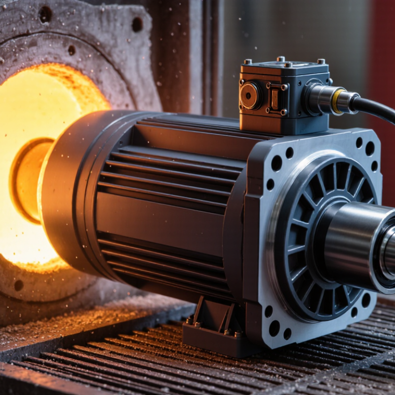
Table of Contents [Hide]
Define the Temperature Range and Operating Environment
Defining the temperature range is the real starting point for choosing an ultra high temperature servo motor. Do not rely on the room temperature alone. Measure the air around the motor, the mounting surface, and nearby heat sources. A motor beside a furnace may experience radiant heat that sensors fail to capture.
Specify both continuous and peak temperatures. Short exposure to extreme heat can still damage insulation, bearings, seals, and feedback devices. I have seen systems operate correctly during testing, then lose positioning accuracy after several hours of heat soak. That delay is easy to underestimate. Heat accumulates.
The operating environment also shapes the correct motor design. Check humidity, dust, vibration, washdown conditions, and available ventilation. A sealed housing may protect internal parts, but it can also trap heat and reduce torque capacity. Cable insulation and connectors need matching temperature ratings, not just the motor body. The drive system deserves equal attention, because high ambient temperature can shorten its service life.
Use measured data from the actual machine whenever possible. Create a temperature map during the heaviest duty cycle. Then compare those results with the motor’s continuous rating, peak rating, and derating curve. Leave a practical safety margin; however, an excessive margin can increase cost and size without solving the real problem. My early estimates were sometimes too optimistic. Rechecking them with thermal tests produced more reliable decisions. A prototype test under worst-case conditions is worth the effort.