-
PRODUCTS & SERVICESOptimized cooling solutions for modern data centersProducts & ServicesOptimized cooling solutions for modern data centers
-
CAPABILITIESAdvancing liquid cooling technologiesCapabilitiesAdvancing liquid cooling technologies
-
TechnologiesLiquid Cooling InnovationTechnologiesLiquid Cooling Innovation
-
RESOURCESLatest News & InformationResourcesLatest News & Information
-
ABOUTOur history, leadership and ownershipAboutOur history, leadership and ownership
-
CONTACTFacility locations and global operational footprint



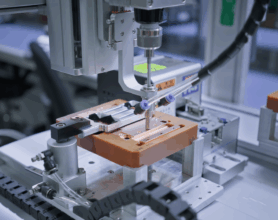



What Is a Cross Slide Table and How Does It Work?
A Cross Slide Table is a compact mechanical platform that moves a workpiece or tool along two perpendicular axes. One axis travels left and right. The other moves forward and backward. Together, these movements support controlled drilling, milling, routing, and inspection work.
Its design is straightforward but demanding. A rigid base supports two sliding plates, usually guided by dovetails, linear rails, or machined ways. Lead screws convert handwheel rotation into measured movement. A graduated collar may show small adjustments, while locking screws help prevent unwanted motion during cutting. On a workshop bench, a user might turn one handwheel by 0.5 millimeters, lock the axis, and make a cleaner hole without repositioning the entire machine.
The wider market explains why this accessory remains relevant. Grand View Research reported that the global machine tools market reached approximately USD 102.9 billion in 2023. The report also identified automation and precision manufacturing as continuing growth factors. In addition, the International Federation of Robotics recorded 541,302 industrial robot installations worldwide in 2023. These figures do not measure Cross Slide Table sales directly. That limitation matters.
Small tables still serve manual mills, drill presses, lathes, and educational machines. They can also support prototype work where a full CNC system would be excessive. However, accuracy depends on more than the product label. Backlash, table deflection, lubrication, clamping force, and operator technique all affect results. ISO 230-2 principles for machine-tool positioning accuracy offer useful guidance, although many low-cost tables are not tested to that standard. The practical lesson is simple: choose measurable rigidity and repeatability, not impressive packaging alone.
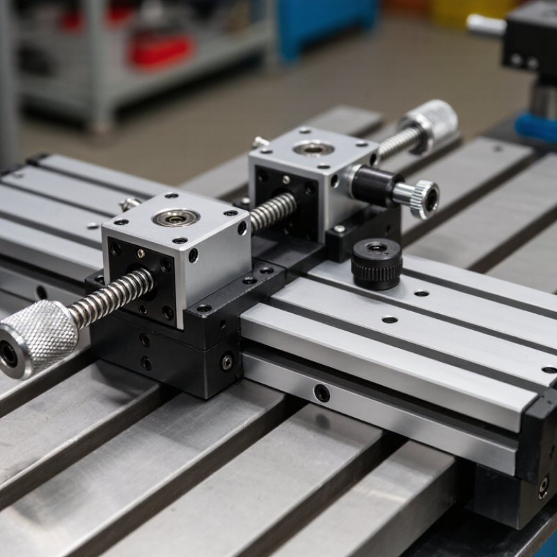
Table of Contents [Hide]
Cross Slide Table Definition: Two-Axis Positioning with X–Y Travel
What Is a Cross Slide Table and How Does It Work?
A cross slide table is a compact machine tool platform that provides two-axis positioning. Its X–Y travel lets a workpiece move horizontally and sideways across a fixed reference point. One axis usually moves left to right, while the second moves front to back. Handwheels, lead screws, and calibrated scales control these movements. Some tables use linear bearings, while others rely on fitted dovetail ways.
In practical machining, the table supports drilling, milling, slotting, and light inspection work. An operator secures the material with clamps or a small vise. Turning the X-axis handwheel shifts the part precisely along one direction. The Y-axis then adjusts its crosswise position. Locking screws help reduce movement during cutting. Small adjustments matter. Even a slight clamp shift can spoil a hole pattern.
Accuracy depends on construction, adjustment, and user technique. Backlash in the lead screw can create unwanted travel when the handwheel direction changes. I usually approach the final measurement from one direction and verify it with a dial indicator. That habit is useful, but not perfect. Dust, uneven clamping, and worn ways can still affect results. A clean surface and steady, repeatable hand pressure often matter more than impressive scale markings.