-
PRODUCTS & SERVICESOptimized cooling solutions for modern data centersProducts & ServicesOptimized cooling solutions for modern data centers
-
CAPABILITIESAdvancing liquid cooling technologiesCapabilitiesAdvancing liquid cooling technologies
-
TechnologiesLiquid Cooling InnovationTechnologiesLiquid Cooling Innovation
-
RESOURCESLatest News & InformationResourcesLatest News & Information
-
ABOUTOur history, leadership and ownershipAboutOur history, leadership and ownership
-
CONTACTFacility locations and global operational footprint






7 Essential Arm Cylinder Buying Tips for Global Buyers
Buying an Arm Cylinder for global equipment requires more than comparing prices and catalog photographs. The correct choice must match the machine’s load, working pressure, stroke length, mounting space, and operating environment. A cylinder that performs well in a clean workshop may struggle in muddy construction conditions or salty coastal air.
Hydraulic systems consultant Brendan Casey offers a useful reminder: “Hydraulic problems are usually system problems, not component problems.” That principle matters during international purchasing. Buyers should confirm bore and rod diameters, retracted and extended lengths, port sizes, seal materials, and allowable side loading. Small dimensional errors can stop installation. They can also create leaks, uneven movement, or premature rod wear.
The seven essential buying tips in this guide focus on practical decisions. They cover application data, supplier capability, material quality, testing, documentation, shipping protection, and after-sales support. Ask for pressure-test records, material details, inspection standards, and clear warranty terms. Check whether the supplier can provide replacement seals and technical drawings years later.
Do not trust a polished quotation alone. Verify the details.
Global sourcing also introduces communication gaps, changing delivery schedules, and unclear specifications. Even experienced buyers miss one important measurement. A simple drawing review can prevent an expensive return shipment. Yet no checklist removes every risk. Field conditions are often messier than the original design brief. Careful questions, documented approvals, and realistic performance expectations make an Arm Cylinder purchase more reliable.
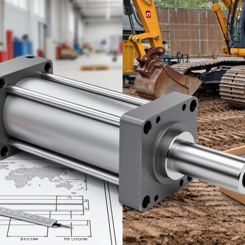
Table of Contents [Hide]
Define Load, Stroke and Bore for 160–250 bar Hydraulic Duty
7 Essential Arm Cylinder Buying Tips for Global Buyers
Define Load, Stroke and Bore for 160–250 bar Hydraulic Duty
Start with the real load, not the machine’s brochure figure. Include attachment weight, material impact, friction, and slope-related forces. Static loads rarely describe working conditions accurately. I have seen cylinders selected from peak pressure alone, then struggle during sudden bucket stops. Record both pushing and pulling loads before requesting quotations.
At 160–250 bar, bore size determines theoretical pushing force. Use this practical relationship: force equals pressure multiplied by piston area. A larger bore may increase force, but it also increases oil volume and operating speed demands. Rod diameter matters during pulling loads and compression. Check buckling risk when the stroke is long. A 100 mm stroke and a 1,000 mm stroke need different structural checks. Do not treat them as interchangeable.
Specify the usable stroke, closed length, mounting style, and pin diameter. Measure the arm’s actual pivot movement, including clearance at both ends. Side loading is a common mistake. Cylinders are designed mainly for axial force, while misalignment can damage seals and pins. Select seals for the fluid, temperature, contamination, and duty cycle. Ask for pressure testing records and material information. A small safety margin is sensible, but an oversized cylinder can slow the system and waste energy. My own early estimates sometimes ignored return-side force, which changed the result considerably. Recheck the calculation with a hydraulic engineer before production.