-
PRODUCTS & SERVICESOptimized cooling solutions for modern data centersProducts & ServicesOptimized cooling solutions for modern data centers
-
CAPABILITIESAdvancing liquid cooling technologiesCapabilitiesAdvancing liquid cooling technologies
-
TechnologiesLiquid Cooling InnovationTechnologiesLiquid Cooling Innovation
-
RESOURCESLatest News & InformationResourcesLatest News & Information
-
ABOUTOur history, leadership and ownershipAboutOur history, leadership and ownership
-
CONTACTFacility locations and global operational footprint







How to Choose the Right Aluminum Extrusion Die
Choosing an Aluminum Extrusion Die is not a small tooling decision. It shapes profile accuracy, surface quality, production speed, and the amount of scrap on the press floor. The International Aluminium Institute has projected that global aluminium demand could grow by nearly 40% by 2030 compared with 2020 levels. That growth raises the stakes for manufacturers: a die must support reliable output, not merely produce one acceptable sample.
Start with the profile itself. Wall thickness, hollows, corners, and dimensional tolerances all affect die design. Alloy, billet temperature, press capacity, and target production volume matter too. A thin-walled channel may need different bearing lengths and metal flow control than a solid bar. Small details count. Even a sharp transition can create uneven flow, die wear, or visible surface marks.
This guide explains how to match die type and design to the job, then weigh material, lead time, cost, and maintenance. Experienced die makers can help interpret drawings and flag difficult features before tooling begins. Ask for evidence from similar profiles, including trial results and expected die life. Numbers help, but they do not tell the whole story. Real production conditions can expose assumptions that looked sound on paper. Choosing well takes technical review, clear requirements, and a willingness to revise the design when the first trial reveals a weakness.
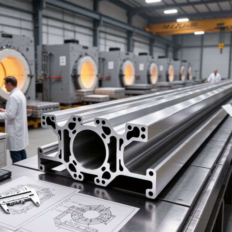
Table of Contents [Hide]
Identify the Profile Geometry and Dimensional Requirements
Before selecting an aluminum Extrusion Die, study the profile drawing rather than judging the outline alone. Note the overall width and height, wall thickness, corner radii, and any grooves or narrow slots. These details affect metal flow through the die. A thin wall beside a heavy section may fill unevenly, even when the outside dimensions look simple. Small features matter.
Mark which dimensions are critical for assembly and which allow normal production variation. A sliding channel may need tighter control than a concealed trim edge. Specify tolerances clearly, and check whether they apply across the full profile or only at certain points. For hollow shapes, identify internal openings and the bridges that form them. These can influence die design and require careful review of strength and flow. A clean, dimensioned drawing helps the die maker assess feasibility before tooling begins.
It is tempting to perfect every measurement on paper. That can be misleading. Compare the drawing with the part’s actual use, mating components, and finishing process. Anodizing or coating may affect fit, so include those requirements early. If a dimension is uncertain, flag it instead of guessing. A physical sample or prototype review can reveal interference that a drawing misses. Revise the specification when needed; a small correction now is usually easier than adjusting a production die later.
| Profile Geometry or Requirement | Details to Identify | Typical Die Consideration | Why It Matters |
|---|---|---|---|
| Solid profile | One continuous cross-section with no enclosed internal voids; record overall width, height, wall thickness, and corner radii. | A solid die is commonly used. Check bearing lengths and metal flow around thick and thin regions. | Uneven section thickness can cause different flow rates, twisting, or dimensional variation. |
| Hollow profile | One or more enclosed cavities, including the number, shape, and minimum size of each void. | A porthole or bridge die is often used; assess mandrel support, weld chambers, and metal flow balance. | The die must form the cavity while maintaining adequate support and sound pressure welds. |
| Semihollow profile | A partially enclosed opening with a narrow gap; specify the opening width and surrounding wall thickness. | Determine whether a solid-die approach is feasible or whether a hollow-style die design is needed. | The opening-to-depth relationship affects die strength, flow, and the risk of distortion. |
| Wall thickness | Define nominal, minimum, and maximum thicknesses, including local transitions and thin webs. | Review die strength and flow balance; avoid abrupt thickness changes where the design permits. | Very thin or uneven walls can be difficult to fill consistently and may increase scrap or correction work. |
| Overall dimensions | Specify the outside envelope, critical internal dimensions, and measurement locations. | Check whether the profile fits the press and die limits, including billet size and container capacity. | Profile size influences press selection, die layout, and achievable production rate. |
| Dimensional tolerances | State the required tolerances for width, height, wall thickness, openings, and functional interfaces. | Set die dimensions with allowance for process effects, including elastic recovery and thermal conditions. | Clear, measurable tolerances help prevent over-specification and ensure the part fits its assembly. |
| Corner radii and edges | Identify internal and external radii, sharp-edge requirements, and any edge breaks. | Include practical radii in the die design where possible; very sharp corners may be difficult to maintain. | Radii can improve metal flow, reduce stress concentration, and support more consistent production. |
| Asymmetry and section balance | Mark off-center features, one-sided projections, unequal wall thicknesses, and long unsupported legs. | Balance flow using suitable bearing design and die layout; plan for trial measurements and adjustment. | Unbalanced flow can cause bow, twist, or uneven exit speed across the profile. |
| Material and temper | Specify the aluminum alloy, temper, and applicable material specification. | Confirm that the die design and press conditions are appropriate for the selected alloy and production requirements. | Alloy and temper affect extrusion behavior, achievable properties, and downstream processing. |
| Length, straightness, and twist | Define cut length and acceptable limits for bow, twist, and straightness, along with inspection methods. | Consider die exit balance and the planned stretching, straightening, and cutting operations. | Profile dimensions may change during cooling and finishing, so final acceptance should reflect the finished condition. |