-
PRODUCTS & SERVICESOptimized cooling solutions for modern data centersProducts & ServicesOptimized cooling solutions for modern data centers
-
CAPABILITIESAdvancing liquid cooling technologiesCapabilitiesAdvancing liquid cooling technologies
-
TechnologiesLiquid Cooling InnovationTechnologiesLiquid Cooling Innovation
-
RESOURCESLatest News & InformationResourcesLatest News & Information
-
ABOUTOur history, leadership and ownershipAboutOur history, leadership and ownership
-
CONTACTFacility locations and global operational footprint




China Top Compensation Capacitors Manufacturers?
China has become a major sourcing base for Compensation Capacitors used in power-factor correction, motor drives, lighting, and industrial control systems. However, production scale does not automatically prove product quality. Buyers need stronger evidence.
Power-electronics engineer Laszlo Balogh offers a practical reminder: “The capacitor is not an ideal component.” This principle matters during supplier evaluation. A reliable manufacturer should explain dielectric selection, rated voltage, capacitance tolerance, dissipation factor, thermal endurance, and expected service life. These details reveal more than a polished product catalog.
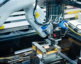
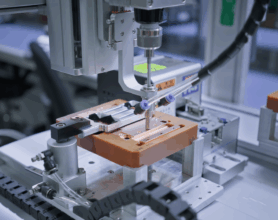
The leading China-based manufacturers usually combine automated winding, controlled impregnation, laser marking, and electrical testing. Their facilities should verify capacitance, insulation resistance, self-healing behavior, and failure performance under elevated temperatures. Factory photographs are useful, but traceable test reports are more convincing. Certifications also require careful checking. ISO documentation alone does not guarantee stable Compensation Capacitors.
Application fit remains critical. A capacitor designed for an air-conditioning motor may not suit a high-frequency converter. Film construction, terminal design, cooling conditions, and harmonic exposure can change the selection completely. Small details matter.
This article introduces China’s top Compensation Capacitors manufacturers through a practical purchasing lens. It considers engineering capability, customization, quality control, delivery consistency, and after-sales support. Some suppliers may look impressive online yet provide limited technical data. That weakness should not be ignored. A better shortlist comes from samples, datasheets, factory audits, and long-term performance evidence. No ranking is permanent. Market conditions, materials, and manufacturing discipline can change.
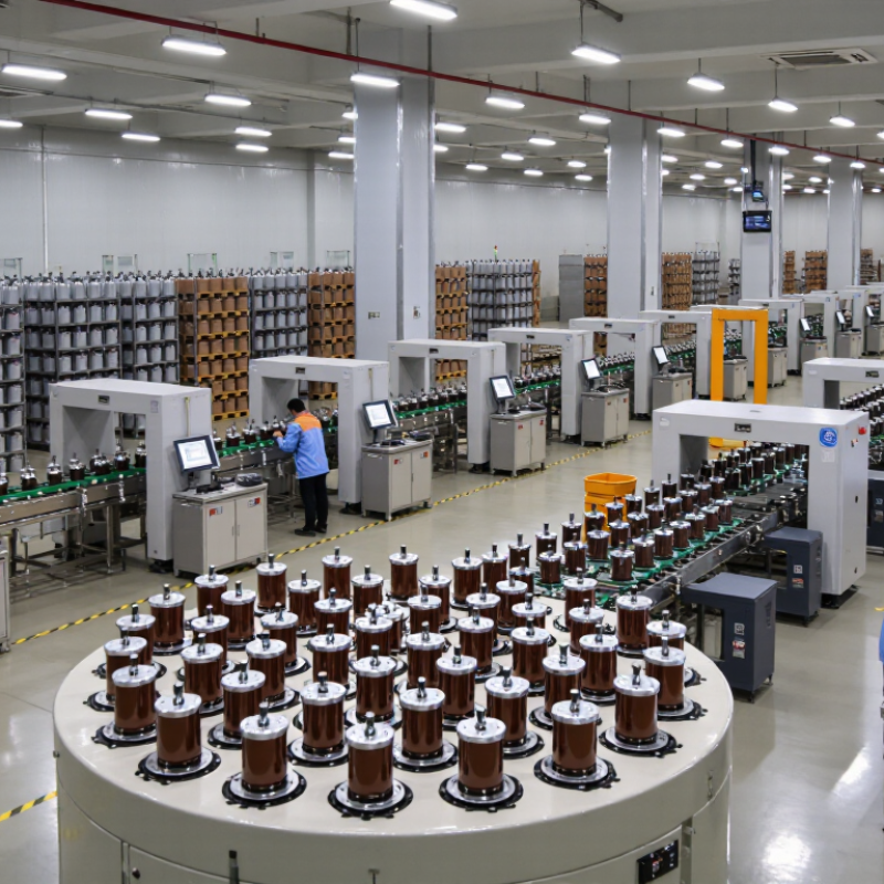
Table of Contents [Hide]
Compensation Capacitors Explained: kvar Ratings, Power Factor, and 50/60 Hz
China’s compensation capacitor manufacturers serve factories, buildings, and utility projects worldwide. Their products correct reactive power and reduce unnecessary current in electrical systems. The key rating is kvar, not simply capacitance. A higher kvar value supplies more reactive support, but oversizing can create leading power factor and unstable operation.
Power factor shows how effectively equipment uses supplied electricity. Motors with low power factor draw more current, warming cables and transformers. Capacitors offset this inductive demand.
Engineers often estimate required correction with
Qc = P(tan φ1 − tan φ2)
This calculation needs real load data, not a nameplate guess. A perfect power-factor target is not always wise. Small errors remain possible.
Tips:
Check rated voltage, kvar output, temperature limits, and discharge time. Confirm 50 Hz or 60 Hz suitability before ordering. Systems with variable-speed drives may need detuned reactors, because harmonics can overheat ordinary capacitor units. Ask manufacturers for test reports, tolerance data, enclosure details, and continuous-duty ratings. Inspect terminal temperature during commissioning. It catches problems early. A reliable supplier should explain aging, switching frequency, and maintenance intervals clearly, rather than promising unrealistic savings.