-
PRODUCTS & SERVICESOptimized cooling solutions for modern data centersProducts & ServicesOptimized cooling solutions for modern data centers
-
CAPABILITIESAdvancing liquid cooling technologiesCapabilitiesAdvancing liquid cooling technologies
-
TechnologiesLiquid Cooling InnovationTechnologiesLiquid Cooling Innovation
-
RESOURCESLatest News & InformationResourcesLatest News & Information
-
ABOUTOur history, leadership and ownershipAboutOur history, leadership and ownership
-
CONTACTFacility locations and global operational footprint







What Is an MPO Cable and How Does It Work?
An MPO Cable is a high-density fiber assembly designed to carry multiple optical signals through one connector. MPO means Multi-fiber Push-On, describing its compact, multi-fiber interface. Instead of using one fiber per connector, it groups several fibers into a single ferrule. This design saves rack space and simplifies high-speed network deployment. Small footprint, large capacity.
Inside an MPO Cable, individual fibers are arranged in precise rows. The connector’s guide pins help align matching fibers during connection. When the plug enters an MPO adapter, each fiber meets its corresponding position. Optical transceivers then convert electrical data into light and send it through parallel fiber channels. A 12-fiber cable may support different transmission methods, depending on the transceiver and network design. Fiber count alone does not determine total bandwidth.
In practical installations, performance depends on more than the cable label. Technicians check polarity, key orientation, connector type, and fiber mapping before deployment. They also measure insertion loss and return loss with calibrated test equipment. A clean end face matters. Dust can weaken optical signals and create intermittent faults. It is easy to treat an MPO Cable as plug-and-play, but that assumption often fails in dense data centers. The concept is straightforward. Field work is not.
This guide explains what an MPO Cable is, how its internal fibers carry data, and where its design fits within modern fiber networks. It also considers common connector configurations, polarity methods, testing practices, and installation limitations. Some details vary by manufacturer and application, so specifications should be verified before purchase or deployment.
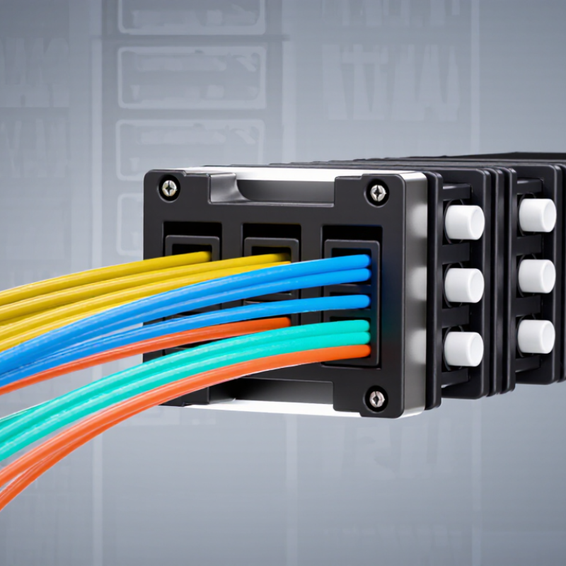
Table of Contents [Hide]
MPO Cable Definition and Core Components
An MPO cable is a pre-terminated fiber assembly designed to connect many optical channels through one compact interface. MPO means Multi-fiber Push-On. Unlike a duplex fiber cable, it carries several fibers inside a single connector body. This design helps reduce installation time and cable congestion in high-density network cabinets.
Its core components include the MPO connector, fiber array, guide pins, key, housing, and protective jacket. The connector holds the fibers in a precise row. Guide pins align the mating surfaces, while the key controls the connector’s orientation. Each fiber can transmit data independently. In a typical 12-fiber assembly, six transmit and six receive fibers may support parallel communication. However, the exact use depends on the network equipment and polarity method.
The cable itself may contain single-mode or multimode fiber. Single-mode fiber suits longer links and tighter performance requirements. Multimode fiber is often practical for shorter connections inside buildings. Polarity deserves careful attention. If the transmit and receive positions do not match, the link may remain dark. That mistake is surprisingly common. Technicians should inspect end faces, verify fiber counts, and test insertion loss before deployment. A clean connector can still fail when its polarity is wrong. This is why labeling and test records matter, even for short cable runs. Some installations also require angled or flat polished ends, depending on the mating components. The specification should never be guessed.