-
PRODUCTS & SERVICESOptimized cooling solutions for modern data centersProducts & ServicesOptimized cooling solutions for modern data centers
-
CAPABILITIESAdvancing liquid cooling technologiesCapabilitiesAdvancing liquid cooling technologies
-
TechnologiesLiquid Cooling InnovationTechnologiesLiquid Cooling Innovation
-
RESOURCESLatest News & InformationResourcesLatest News & Information
-
ABOUTOur history, leadership and ownershipAboutOur history, leadership and ownership
-
CONTACTFacility locations and global operational footprint





What Is an Oilfield Mud Pump and How Does It Work?
An Oilfield Mud Pump is the pressure engine behind rotary drilling. It moves drilling fluid from surface tanks into the wellbore. This fluid cools the bit, carries rock cuttings upward, and supports wellbore control. Without reliable circulation, drilling progress can slow quickly.
The principle is straightforward. A triplex or quintuplex pump uses pistons, liners, valves, and a crankshaft to create positive displacement. During the suction stroke, the pump draws mud through the inlet manifold. During the discharge stroke, it forces mud through the standpipe and drillstring. The fluid then exits through the bit nozzles and returns through the annulus. Pulsation dampeners help reduce pressure fluctuations. Small liner wear can still change flow accuracy.
The International Energy Agency’s Oil 2024 report forecasts global oil demand to rise by about 3.2 million barrels per day between 2023 and 2029. That outlook does not guarantee new drilling activity, but it shows why dependable drilling systems remain commercially important. Baker Hughes International Rig Count data also provides a widely used indicator of global drilling activity. API Specification 7K and API Recommended Practice 54 provide important guidance for drilling equipment and safe operations.
Real performance depends on mud density, viscosity, solids content, stroke rate, and well depth. A pump rated for high pressure may not deliver stable output with poorly maintained valves or damaged liners. The basic diagram is useful, but incomplete. Field inspections, pressure tests, maintenance records, and trained judgment matter more than brochure numbers. This article explains how an Oilfield Mud Pump works and why each component affects drilling reliability.
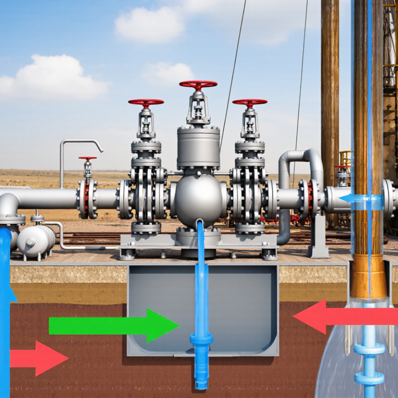
Table of Contents [Hide]
Oilfield Mud Pump: Definition, Purpose, and Role in Drilling
What Is an Oilfield Mud Pump and How Does It Work?
An oilfield mud pump is a high-pressure, positive-displacement pump used in drilling operations. It moves drilling fluid, commonly called mud, from surface tanks into the drillstring. The fluid then travels through the pipe and exits through nozzles in the drill bit.
The pump’s main purpose is circulation. Drilling mud cools the bit, carries rock cuttings back to the surface, and helps control underground pressure. It also supports the borehole wall in suitable formations.
Inside the pump, pistons or plungers draw fluid through suction valves and force it through discharge valves. The flow is pulsing, not perfectly smooth. Pulsation dampeners help reduce pressure variation.
A mud pump must deliver reliable pressure and volume for changing well conditions. Operators watch discharge pressure, stroke rate, liner condition, valve movement, and fluid leaks. Even a small seal failure can reduce circulation and create an avoidable maintenance problem. Field experience shows that pump performance depends on more than horsepower. Mud density, abrasive solids, temperature, and suction conditions all matter.
The pump does not drill the formation by itself. It supports the entire hydraulic system. If circulation becomes weak, cuttings may settle, bit cooling can decline, and pressure control becomes more difficult. A design may look efficient on paper, yet real performance can change quickly underground. That is why inspection records, measured data, and trained judgment remain essential.