-
PRODUCTS & SERVICESOptimized cooling solutions for modern data centersProducts & ServicesOptimized cooling solutions for modern data centers
-
CAPABILITIESAdvancing liquid cooling technologiesCapabilitiesAdvancing liquid cooling technologies
-
TechnologiesLiquid Cooling InnovationTechnologiesLiquid Cooling Innovation
-
RESOURCESLatest News & InformationResourcesLatest News & Information
-
ABOUTOur history, leadership and ownershipAboutOur history, leadership and ownership
-
CONTACTFacility locations and global operational footprint




What Is an RMU Electrical Panel and How Does It Work?
An Rmu Electrical Panel is a compact medium-voltage assembly used to connect, protect, and isolate sections of a distribution network. It often serves ring-shaped networks, where power can reach a site from more than one direction. Inside the metal enclosure, operators may find load-break switches, circuit breakers, fuses, busbars, and earthing switches. The exact arrangement varies. Some units use gas insulation; others use solid insulation or air-based designs. It is not one universal box.
Electrical engineer and safety author John Cadick’s guidance can be paraphrased this way: “Reliable switching depends on understanding equipment limits, condition, and operating steps.” This is a paraphrase, not a verbatim quotation. That distinction matters when technical claims need checking. In operation, a switch directs or interrupts current, while protective devices help clear faults. Interlocks can prevent certain unsafe switching sequences, but they do not replace training or careful procedures. A technician may inspect position indicators, labels, and cable terminations before work begins. Small details matter. A misleading indicator or unclear diagram can complicate an otherwise routine task. This introduction will explain the panel’s main components, how current moves through it, and where protection fits. It will also note what a basic overview cannot establish: the correct operating steps depend on the specific model, site design, and manufacturer’s documentation.
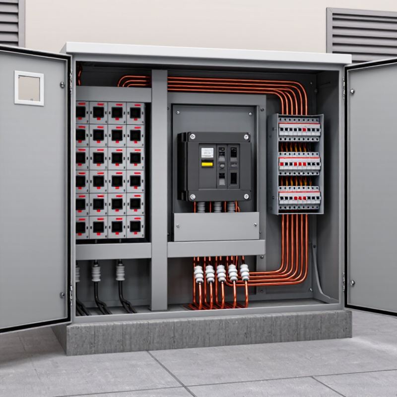
Table of Contents [Hide]
What an RMU Electrical Panel Is and Where It Fits in a Power Network
An RMU, or ring main unit, is compact medium-voltage switchgear used in local electricity distribution. It sits between a primary substation and distribution transformers, often inside a street-side cabinet or a building’s electrical room. It is not a transformer. Its job is to switch, protect, and isolate sections of the network. A typical unit combines incoming and outgoing feeder switches with a transformer-protection switch or circuit breaker. The exact arrangement depends on the network design and utility requirements.
In a ring network, power can reach a local substation from either direction. If a cable section develops a fault, operators can isolate it and restore supply through another route, where the network allows. The practical value of the RMU is that it helps manage a small, defined point in a much larger system.
The International Energy Agency’s 2023 report, Electricity Grids and Secure Energy Transitions, says annual grid investment must rise to more than $600 billion by 2030, from about $300 billion today. This figure covers grids broadly, not RMUs alone.
Real sites are less tidy than diagrams suggest. Space, fault levels, maintenance access, and future load all affect equipment selection. A compact unit may save room, but it does not remove the need for sound protection coordination.