-
PRODUCTS & SERVICESOptimized cooling solutions for modern data centersProducts & ServicesOptimized cooling solutions for modern data centers
-
CAPABILITIESAdvancing liquid cooling technologiesCapabilitiesAdvancing liquid cooling technologies
-
TechnologiesLiquid Cooling InnovationTechnologiesLiquid Cooling Innovation
-
RESOURCESLatest News & InformationResourcesLatest News & Information
-
ABOUTOur history, leadership and ownershipAboutOur history, leadership and ownership
-
CONTACTFacility locations and global operational footprint







What Is a Strut Channel Machine and How Does It Work?
A Strut Channel Machine is a specialized roll-forming system that converts flat steel coil into strong, U-shaped support channels. These channels appear in electrical installations, HVAC systems, solar structures, and industrial framing. The machine does more than bend metal. It controls feeding, punching, forming, cutting, and sometimes automatic stacking.
Picture a steel coil entering the line. Rollers guide it through several forming stations. Each station changes the profile slightly, reducing stress and protecting the channel’s dimensions. A punching unit may create regular slots or holes before a flying saw cuts each section to length. Small errors can multiply quickly. A misaligned roller may produce twisted channels, uneven slots, or damaged edges.
“Consistent forming depends on disciplined setup, not speed alone,” says Martin Keller, a senior roll-forming engineer with practical experience in structural profile production. His observation is worth remembering. Many buyers focus on output per minute, yet repeatable accuracy often matters more than impressive speed.
This guide explains what a Strut Channel Machine is, how its main components work, and why setup affects product quality. It also considers material thickness, channel dimensions, punching patterns, tooling life, and maintenance requirements. The process can look straightforward. It is not always. Operators must watch coil tension, roller alignment, lubrication, and cutting accuracy throughout production.
A reliable machine should produce clean profiles repeatedly, not merely complete one successful trial. That distinction deserves attention.
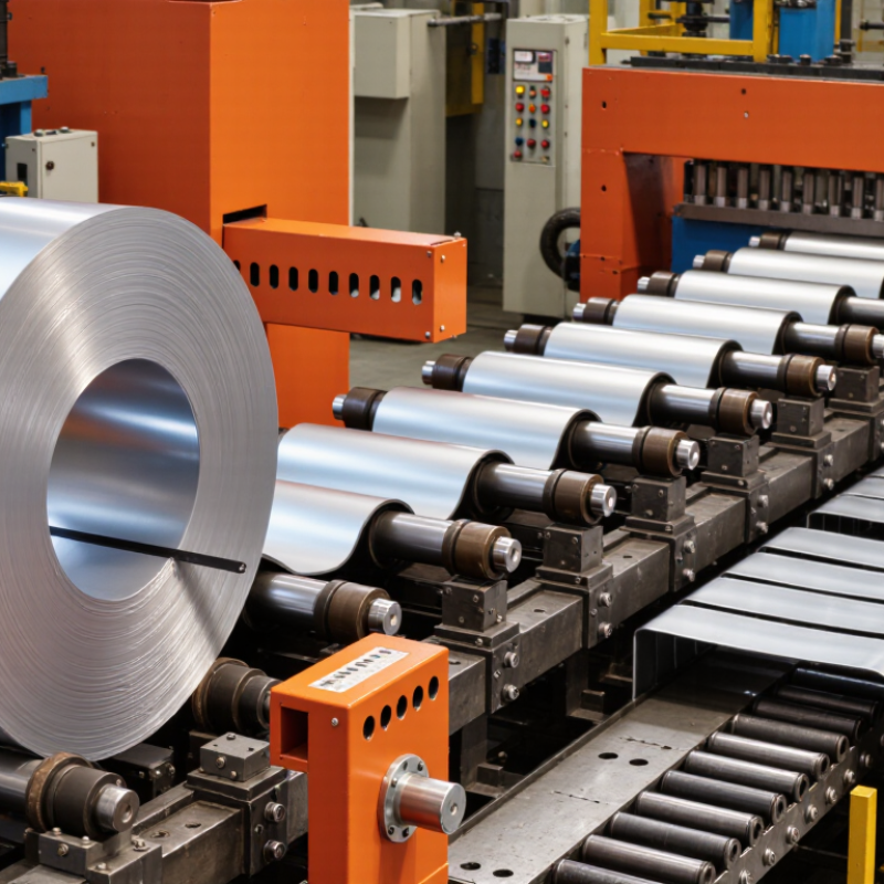
Table of Contents [Hide]
Strut Channel Geometry: Common 41 × 41 mm and 41 × 21 mm Profiles
A strut channel machine converts coiled steel into structural support channels through continuous roll forming. The line normally includes a decoiler, leveler, punching unit, forming stands, and flying or stop-cut equipment. Each station changes the strip gradually, reducing distortion and preserving hole alignment. According to the USGS Mineral Commodity Summaries 2024, global crude steel production reached about 1.9 billion metric tons in 2023. That scale supports steel availability, but it does not guarantee consistent channel quality.
The 41 × 41 mm profile is widely used when installers need balanced strength and space for threaded rods, clamps, or cable supports. The 41 × 21 mm profile is shallower and lighter, making it suitable for smaller loads and tighter service zones. These dimensions are nominal. Actual performance depends on thickness, corner radius, steel grade, coating, and perforation pattern. The AISI S100 design specification requires engineers to consider local buckling and section properties, not size alone. A thicker 41 × 21 mm channel may outperform a thinner 41 × 41 mm channel in specific conditions. That surprises people.
During production, roll tooling must match the profile’s lips and bends precisely. Small errors can twist the channel or shift mounting holes. In practice, operators should verify width, height, wall thickness, straightness, and hole pitch with calibrated gauges. A useful check is often missed: measure the finished section after cutting, not only during forming. Surface appearance is not enough. Even a clean channel can fail dimensional inspection.
What Is a Strut Channel Machine and How Does It Work? — Strut Channel Geometry: Common 41 × 41 mm and 41 × 21 mm Profiles
| Data Dimension | 41 × 41 mm | 41 × 21 mm | Why It Matters in Machine Production |
|---|---|---|---|
| Nominal outside dimensions | Approximately 41 mm wide × 41 mm deep | Approximately 41 mm wide × 21 mm deep | The roll-forming tooling must maintain the specified channel width and depth throughout the strip-forming process. |
| Typical channel opening | Usually about 22–25 mm, depending on the lip design and material thickness | Usually about 22–25 mm, depending on the lip design and material thickness | The opening provides access for channel nuts, fittings, threaded hardware, and installation adjustments. |
| Common material | Pre-galvanized carbon steel; stainless steel is also used for corrosive environments | Pre-galvanized carbon steel; stainless steel is also used for corrosive environments | Material selection affects corrosion resistance, forming force, tooling wear, and finished-product strength. |
| Common material thicknesses | Approximately 1.5, 2.0, or 2.5 mm, depending on the required load capacity | Approximately 1.5 or 2.0 mm, depending on the required load capacity | A decoiler, straightener, and roll-forming stands must be selected for the specified strip thickness and yield strength. |
| Typical stock length | Commonly supplied in 3 m or 6 m lengths; custom cut lengths are possible | Commonly supplied in 3 m or 6 m lengths; custom cut lengths are possible | A cut-to-length unit normally uses an encoder or measuring system to produce repeatable finished lengths. |
| Section shape | Deep U-shaped channel with inward-returning lips | Shallow U-shaped channel with inward-returning lips | The roll-forming line progressively bends the flat strip through multiple stations to create the web, side walls, and lips. |
| Typical uses | Pipe supports, cable-tray supports, equipment frames, mechanical services, solar-support subframes, and heavier-duty assemblies | Light-duty cable supports, conduit brackets, small pipe supports, partitions, and compact framing assemblies | The selected profile depends on span, load, deflection limits, installation space, and the type of fittings used. |
| Relative load capability | Generally higher bending stiffness than the 41 × 21 mm profile when material and thickness are comparable | Generally lower bending stiffness than the 41 × 41 mm profile when material and thickness are comparable | Actual capacity depends on steel grade, thickness, span, support spacing, connection method, holes, and applied loading. |
| Perforation options | Plain, slotted, or punched configurations are commonly produced | Plain, slotted, or punched configurations are commonly produced | Pre-punching can be integrated before roll forming, while post-form punching can be used when hole alignment requires it. |
| Typical machine sequence | Coil loading → decoiling → leveling → optional punching → roll forming → cut-to-length → stacking or bundling | Each stage controls a specific production variable, including strip tension, flatness, hole position, profile geometry, and finished length. | |
| Forming method | Cold roll forming with several driven forming stands | Each stand performs a small angular bend, reducing distortion and allowing the channel to be formed continuously from coil stock. | |
| Quality checks | Outside dimensions, opening width, straightness, twist, hole pitch, cut length, surface condition, and coating integrity | Dimensional inspection confirms that the finished channel fits standard nuts, fittings, brackets, and installation hardware. | |
| Important design note | Nominal dimensions do not define structural capacity by themselves | Engineering verification should use the actual section properties, steel grade, thickness, support conditions, and applicable design standard. | |
Note: Dimensions and thicknesses shown are common industry ranges rather than a universal specification. Exact geometry, tolerances, hole patterns, coating mass, and load ratings should be confirmed against the project drawing or applicable standard.