-
PRODUCTS & SERVICESOptimized cooling solutions for modern data centersProducts & ServicesOptimized cooling solutions for modern data centers
-
CAPABILITIESAdvancing liquid cooling technologiesCapabilitiesAdvancing liquid cooling technologies
-
TechnologiesLiquid Cooling InnovationTechnologiesLiquid Cooling Innovation
-
RESOURCESLatest News & InformationResourcesLatest News & Information
-
ABOUTOur history, leadership and ownershipAboutOur history, leadership and ownership
-
CONTACTFacility locations and global operational footprint






7 Tips for Buying the Right Wedge Anchors?
Choosing the right Wedge Anchors is more than matching a bolt to a drilled hole. The concrete may look solid, yet hidden cracks, weak edges, or shallow slabs can change the result. In real installation work, small details often decide whether an anchor remains secure under tension, shear, or vibration. I have seen projects delayed because the anchor diameter was correct, but the embedment depth was not. That mistake is easy to miss before drilling begins.
This guide explains seven practical tips for selecting Wedge Anchors with greater confidence. It considers concrete strength, anchor size, embedment depth, load requirements, corrosion resistance, edge distance, and installation quality. Manufacturer data and recognized engineering standards should guide every decision. Product labels alone are not enough. Check the technical sheet carefully.
Measure twice.
A suitable anchor must match the base material and the actual load, not an assumed condition. Outdoor projects may require stainless steel or specially coated anchors. Indoor applications still need protection when moisture or chemicals are present. A torque wrench also matters, because insufficient tightening can reduce holding capacity, while excessive torque may damage the fastener or concrete.
Some recommendations depend on site conditions. That is where judgment becomes important. No checklist replaces inspection by a qualified professional when safety-critical connections are involved. This article also acknowledges an uncomfortable point: even experienced installers can overlook substrate differences. Careful preparation remains the most reliable safeguard.
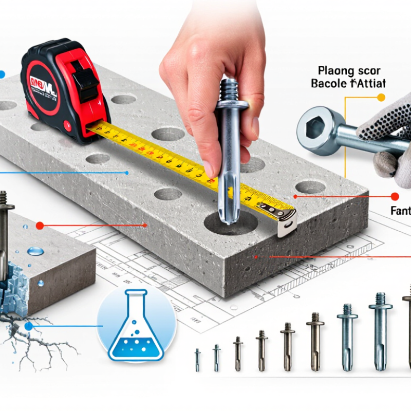
Table of Contents [Hide]
Identify the Base Material and Concrete Condition
Before choosing wedge anchors, identify what lies beneath the drill point. Solid, normal-weight concrete is the usual base material for these anchors. Lightweight concrete, grout-filled block, brick, and hollow units need different fastening methods. I check drawings, site records, and exposed surfaces rather than trusting appearance. Concrete can look sound while containing voids, honeycombing, or shallow edges. That hidden condition matters.
Age alone does not prove strength. A newly placed slab may still be too weak, while an older slab may have reliable capacity. Look for cracks, delamination, spalling, moisture damage, and previous repairs. A visible crack near the hole deserves attention. Cracked concrete may require anchors evaluated for cracked conditions. If the concrete grade is unknown, obtain project records or arrange testing through a qualified professional. Guessing is cheap at first. Repairs are not.
Before installation, scan for reinforcement, conduit, and post-tensioning components where applicable. Keep the required edge distance and spacing stated in the technical data. Drill to the specified diameter and embedment depth, then clean the hole carefully. Dust left inside can reduce expansion and holding power. I have seen installers measure depth but skip cleaning; that shortcut is easy to regret. A torque wrench helps verify installation, but torque is not a substitute for sound concrete. When the base material or condition remains uncertain, pause and document it before buying the anchors.