-
PRODUCTS & SERVICESOptimized cooling solutions for modern data centersProducts & ServicesOptimized cooling solutions for modern data centers
-
CAPABILITIESAdvancing liquid cooling technologiesCapabilitiesAdvancing liquid cooling technologies
-
TechnologiesLiquid Cooling InnovationTechnologiesLiquid Cooling Innovation
-
RESOURCESLatest News & InformationResourcesLatest News & Information
-
ABOUTOur history, leadership and ownershipAboutOur history, leadership and ownership
-
CONTACTFacility locations and global operational footprint






Top 10 Types of Insulated Terminal Lugs for Wiring?
Reliable wiring begins with a small connection that is often overlooked: the terminal lug. Insulated Terminal Lugs protect crimped conductors from accidental contact, moisture, vibration, and short circuits. In a control cabinet, that protection can be as practical as preventing a loose copper strand from touching a metal enclosure. The choice still depends on conductor size, insulation material, temperature rating, and installation conditions.
MarketsandMarkets’ 2024 Wire and Cable Market report estimates the global market at more than USD 200 billion, with continued growth driven by power networks, automation, renewable energy, and electric vehicles. This expansion increases demand for dependable connection hardware. However, wire growth does not automatically guarantee safe terminations. The International Electrotechnical Commission’s IEC 61238-1 standard emphasizes electrical and mechanical performance for compression and mechanical connectors. UL Solutions also highlights proper crimping, material compatibility, and application-specific testing.
That is where this guide becomes useful. It examines ten common types of Insulated Terminal Lugs, including ring, fork, pin, butt, and flag terminals. Each design creates a different balance between installation speed, vibration resistance, serviceability, and current capacity. A ring terminal may remain secure under repeated movement, while a fork terminal allows faster removal during maintenance. Neither choice is universally superior. That point is easy to miss.
Real installations are rarely perfect. Crimp height may vary, tools may wear, and insulation can become brittle near heat sources. Therefore, this overview combines manufacturer guidance, recognized standards, and practical wiring experience. It also encourages careful verification before production use. A suitable lug is not merely one that fits the wire. It must fit the entire electrical environment.
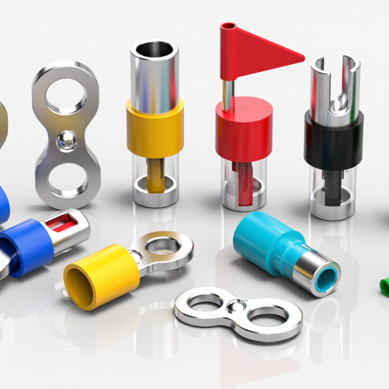
Table of Contents [Hide]
How Insulated Terminal Lugs Are Classified by Connection Method
Insulated terminal lugs are often grouped by shape, but connection method gives electricians a more useful classification. A practical ten-type taxonomy includes crimp, compression, solder, screw-clamp, set-screw, bolted, spring-clamp, push-in, insulation-displacement, and quick-disconnect lugs. Each method changes installation speed, pull-out strength, vibration resistance, and inspection requirements.
Crimp lugs use a controlled die to deform the barrel around the conductor. Compression lugs usually need heavier tooling and suit larger cables. Soldered lugs can seal fine strands, but heat may damage nearby insulation. Screw-clamp and set-screw designs simplify field work, although loose torque remains a real concern. Bolted lugs provide strong joints on busbars. Spring-clamp and push-in types support faster panel assembly. Insulation-displacement lugs pierce insulation directly, while quick-disconnect lugs allow repeated servicing. The connection is the deciding detail.
The International Energy Agency reported that global electricity demand could grow by about 4% in 2024 and 2025, increasing pressure on reliable wiring installation. IEC 61238-1 evaluates mechanical and electrical performance for power cable connectors, while UL 486A-486B addresses wire connectors and terminals. These standards do not make every lug interchangeable. Field experience proves that conductor material, barrel size, crimp profile, and torque must match. I have seen neat-looking joints fail after vibration because the tool was wrong. That shortcut still needs questioning. A transparent inspection record should note the lug type, conductor size, tooling, and applied torque.