-
PRODUCTS & SERVICESOptimized cooling solutions for modern data centersProducts & ServicesOptimized cooling solutions for modern data centers
-
CAPABILITIESAdvancing liquid cooling technologiesCapabilitiesAdvancing liquid cooling technologies
-
TechnologiesLiquid Cooling InnovationTechnologiesLiquid Cooling Innovation
-
RESOURCESLatest News & InformationResourcesLatest News & Information
-
ABOUTOur history, leadership and ownershipAboutOur history, leadership and ownership
-
CONTACTFacility locations and global operational footprint




Top 10 Types of Oilless Reciprocating Compressors
Choosing the right Oilless Reciprocating Compressor begins with understanding its working environment. Pressure, flow, duty cycle, temperature, and air purity all influence performance. A unit feeding a medical-air system faces different demands from one operating beside a dusty packaging line.
Dr. Heinz P. Bloch, a widely published machinery reliability expert, offers a useful reminder: “Reliability is designed in, not inspected in.” That principle fits oil-free compressor selection closely. Sealing materials, piston rings, cylinder coatings, cooling methods, and maintenance access can decide whether equipment performs smoothly or creates repeated downtime.
This guide examines the top 10 types of Oilless Reciprocating Compressor systems used across industrial, laboratory, medical, food-processing, and instrument-air applications. The list considers construction, cooling arrangement, pressure range, portability, and operating purpose. It also highlights practical differences between diaphragm compressors, dry-running piston designs, single-stage models, two-stage units, air-cooled systems, water-cooled systems, and specialized high-pressure configurations.
Small details matter. A warm discharge pipe, uneven vibration, or a cracked seal can reveal a deeper design problem. Quiet operation alone proves little. Neither does a low purchase price.
No ranking is completely universal. A compressor that suits a clean laboratory may struggle in a hot workshop. Some sources also classify compressor types differently, which can make comparisons confusing. That limitation deserves attention.
The following overview aims to make those choices clearer. It connects technical structure with real operating conditions, helping readers judge efficiency, reliability, maintenance needs, and long-term value with greater confidence.
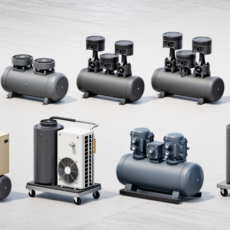
Table of Contents [Hide]
Definition and Operating Principles of Oilless Reciprocating Compressors
Oilless reciprocating compressors compress gas without oil entering the cylinder or compression chamber. A piston moves inside a cylinder, drawing gas through an inlet valve. It then reverses direction and forces the gas through a discharge valve. Sealing rings, low-friction materials, or diaphragms replace oil-based lubrication. Common configurations include single-stage, two-stage, single-acting, double-acting, diaphragm, crosshead, trunk-piston, V-type, W-type, and opposed-piston designs.
The main benefit is cleaner compressed air for medical, laboratory, food, and electronics applications. However, “oilless” does not always mean zero contamination. Wear particles, moisture, and lubricant from bearings can still enter the air stream. ISO 8573-1:2010 evaluates compressed-air purity through particles, water, and oil, so testing should support every specification. The U.S. Department of Energy reports that compressed air can consume about 10% of industrial electricity. Its compressed-air guidance also identifies leakage as a common source of wasted energy, often reaching 20–30% of compressor output. That figure deserves site verification, not blind acceptance.
In operation, piston speed, discharge pressure, clearance volume, and cooling temperature strongly influence efficiency. Two-stage models reduce the pressure burden per cylinder, but add valves, piping, and maintenance points. Diaphragm designs offer strong separation from the process gas, yet their flexible membranes can fatigue. Real installations are less tidy. A clean-room compressor may still need filtration, condensate control, acoustic treatment, and scheduled seal inspections.