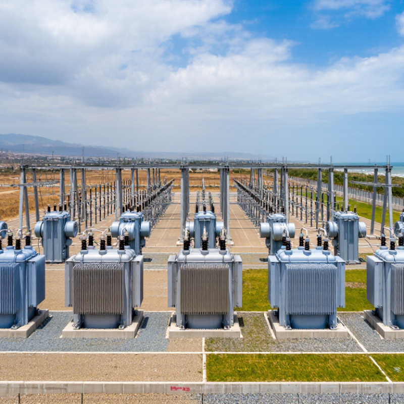
| 1 | Mineral-Oil Distribution Transformer | Urban and rural medium-voltage substations, commercial feeders, and industrial distribution networks. | 100 kVA–5 MVA | 6.6–36 kV / 0.4–11 kV | ONAN; sealed-tank or conservator design; cellulose paper insulation in mineral oil. | Utility earthing method, insulation coordination, tap range, short-circuit withstand, ambient temperature, altitude, and local fire regulations. | Winding resistance, voltage ratio and phase displacement, no-load loss and current, load loss and impedance, applied-voltage test, induced-voltage test, leak and pressure checks. | Commonly 24 months after commissioning or 30 months after shipment, subject to contract terms. | Low purchase cost; prioritize low no-load losses, serviceable bushings, oil-quality monitoring, corrosion protection, and accessible spare parts. |
| 2 | Low-Loss Amorphous-Core Distribution Transformer | Projects with lightly loaded transformers, long operating hours, or regulated energy-efficiency targets. | 50 kVA–2.5 MVA | 6.6–24 kV / 0.4–11 kV | ONAN; oil-immersed; amorphous-metal core designed to reduce no-load loss. | Applicable minimum-efficiency rules, utility loss-capitalization method, harmonic loading, voltage regulation, and metering requirements. | Routine electrical tests plus verified no-load loss, load loss, impedance, temperature-rise test where specified, sound-level test, and dielectric tests. | Usually 24 months after commissioning or as negotiated with an extended-life option. | Higher initial price can be offset by lower core losses over 20–30 years; calculate savings using the actual load profile and local electricity tariff. |
| 3 | Large Utility Power Transformer | Transmission substations, grid interconnections, and high-capacity generation or load centers. | 20–1,000 MVA | 66–550 kV and above, depending on system design | ONAN/ONAF/OFAF; conservator or sealed system; on-load tap changer commonly used for voltage control. | System fault level, neutral insulation, lightning and switching impulse levels, tap-changer duty, parallel operation, transport limits, and utility protection philosophy. | Ratio and vector group, winding resistance, impedance and load loss, no-load loss, applied and induced voltage, lightning impulse, temperature rise, sound level, partial discharge, oil tests, and OLTC functional tests where applicable. | Commonly 24 months after commissioning, with negotiated extensions for major components and accessories. | Transport and outage risk are major cost drivers; evaluate efficiency, redundancy, online monitoring, oil containment, spare-part strategy, and repair lead time. |
| 4 | Renewable-Energy Collector Transformer | Solar parks, wind farms, battery-energy-storage plants, and medium-voltage collector systems. | 1.6–10 MVA per unit | 0.69–1.5 kV / 10–36 kV | Oil-immersed ONAN or KNAN; compact skid-mounted design; optional ester fluid for enhanced fire and environmental performance. | Converter harmonics, rapid load variation, bidirectional power flow, reactive-power operation, energization inrush, grounding, protection coordination, and plant-level voltage-control requirements. | Routine transformer tests, impedance and losses, temperature rise, harmonic or non-sinusoidal load assessment where specified, sound level, dielectric tests, pressure or leak test, and accessory functional tests. | Typically 24–60 months for renewable projects, often linked to commissioning and availability obligations. | Focus on efficiency under the project load profile, inverter compatibility, corrosion protection, cooling reliability, spare units, and the cost of production losses during failure. |
| 5 | Generator Step-Up Transformer | Thermal, hydro, wind, solar, and other generation plants connecting generators to the transmission or sub-transmission grid. | 10–800 MVA | 6.6–27 kV / 66–550 kV | ONAN/ONAF/OFAF; oil-immersed; fixed ratio or tap changer according to generator and grid requirements. | Generator terminal voltage, neutral grounding, transient recovery, over-fluxing, harmonics, system fault current, insulation coordination, and synchronization requirements. | Ratio, winding resistance, load and no-load losses, impedance, applied and induced voltage, lightning impulse, partial discharge, temperature rise, sound level, oil quality, and protection/accessory checks. | Normally 24 months after commissioning, with performance guarantees and optional extended service agreements. | Capital cost is less important than availability; assess efficiency, bushing and OLTC reliability, online dissolved-gas monitoring, fire protection, and emergency repair capability. |
| 6 | Dry-Type Cast-Resin Transformer | Indoor substations, high-rise buildings, tunnels, hospitals, data centers, and locations with strict fire or oil-containment restrictions. | 100 kVA–20 MVA | 3.3–36 kV / 0.4–11 kV | AN or AF; cast-resin solid insulation; no liquid oil, with optional forced-air cooling. | Indoor ventilation, fire classification, acoustic limits, humidity and condensation, partial discharge, harmonic heating, enclosure IP rating, and seismic requirements. | Winding resistance, ratio and phase displacement, no-load and load losses, impedance, applied and induced voltage, partial discharge, temperature rise, sound level, and enclosure or accessory checks. | Commonly 24 months after commissioning; longer coverage may apply to monitoring and cooling systems. | Higher purchase cost may be balanced by reduced fire protection, oil handling, and room-containment costs; include ventilation energy and cleaning requirements. |
| 7 | Ester-Fluid Environmental Transformer | Urban substations, environmentally sensitive sites, indoor or semi-indoor installations, and areas with high fire-safety requirements. | 250 kVA–40 MVA | 6.6–66 kV / 0.4–36 kV | ONAN or ONAF; natural or synthetic ester fluid; sealed-tank or conservator arrangement. | Fluid approval, biodegradability or fire-point requirements, temperature-rise limits, compatibility of seals and materials, environmental permits, and local utility acceptance. | Standard routine tests, fluid breakdown voltage and moisture tests, leak and pressure tests, temperature rise, dielectric tests, and verification of fluid and accessory compatibility. | Usually 24 months after commissioning, with fluid-quality obligations defined in the maintenance plan. | Higher fluid and equipment cost may reduce fire-protection, spill-remediation, and environmental-liability costs; confirm fluid replacement and disposal procedures. |
| 8 | Phase-Shifting Transformer | Interconnectors, congested transmission corridors, loop networks, and systems requiring controlled active-power flow. | 50–1,000 MVA | 66–550 kV | Oil-immersed; two-core or multi-core phase-shifting arrangement; on-load tap changer for phase-angle control. | Permitted phase-angle range, circulating current, system stability, fault withstand, OLTC duty, protection interlocking, harmonic performance, and transmission-operator control interfaces. | Routine transformer tests plus phase-angle verification, ratio and impedance by tap position, OLTC operation, temperature rise, short-circuit withstand where specified, impulse tests, partial discharge, and control-system tests. | Commonly 24 months after commissioning, with extended OLTC and control-system support negotiated separately. | High engineering and commissioning cost; evaluate avoided congestion costs, auxiliary power, OLTC maintenance, spare modules, and outage consequences. |
| 9 | Mobile Emergency Substation Transformer | Disaster recovery, temporary grid reinforcement, planned outage support, remote projects, and rapid replacement service. | 5–100 MVA | 33–245 kV, depending on platform and project | Oil-immersed; transportable tank or trailer-mounted package; plug-and-play accessories and compact radiators. | Road and rail transport limits, lifting points, temporary grounding, connection interfaces, protection settings, climate conditions, rapid energization procedures, and local operating permits. | Routine electrical tests, transport vibration or securing inspection, leak and pressure checks, ratio and impedance, dielectric tests, accessory function tests, and site re-commissioning tests. | Often 12–24 months after commissioning, with separate rental, refurbishment, or emergency-response terms. | Evaluate availability value rather than purchase price alone; include transport, deployment time, storage, inspection, spare cables, connectors, and operator training. |
| 10 | Traction and Industrial Rectifier Transformer | Railway traction substations, electrolysis, steel, mining, data-intensive industry, and other rectifier or high-harmonic loads. | 1–100 MVA | 6.6–132 kV / 0.4–36 kV DC-side arrangements | Oil-immersed or dry-type; multi-winding, phase-shifting, or rectifier-duty design with enhanced harmonic capability. | Rectifier pulse number, harmonic current, DC bias, cyclic overload, voltage unbalance, stray-flux heating, insulation coordination, grounding, and railway or industrial authority requirements. | Ratio and phase displacement for all windings, losses, impedance, temperature rise under specified duty, dielectric tests, partial discharge where applicable, harmonic-load verification, sound level, and accessory tests. | Typically 24 months after commissioning, with duty-cycle and overload conditions explicitly stated in the contract. | Select for the real duty cycle, not only nameplate MVA; assess harmonic losses, cooling energy, vibration, maintenance access, rectifier compatibility, and downtime cost. |