-
PRODUCTS & SERVICESOptimized cooling solutions for modern data centersProducts & ServicesOptimized cooling solutions for modern data centers
-
CAPABILITIESAdvancing liquid cooling technologiesCapabilitiesAdvancing liquid cooling technologies
-
TechnologiesLiquid Cooling InnovationTechnologiesLiquid Cooling Innovation
-
RESOURCESLatest News & InformationResourcesLatest News & Information
-
ABOUTOur history, leadership and ownershipAboutOur history, leadership and ownership
-
CONTACTFacility locations and global operational footprint





What Are the Top Types of PCB Micro Switches?
A Pcb Micro Switch may be tiny, but its choice can affect how a device feels and performs. A mouse button needs a crisp click. A control panel may need a switch that stays in position. These differences explain why “micro switch” can describe several compact switch styles, not just one design. The exact meaning also varies between suppliers. That label can be confusing.
This guide looks at common PCB-mounted options, including tactile, slide, DIP, pushbutton, and miniature snap-action switches. Each type serves a different purpose. Tactile switches suit brief, momentary inputs, while slide switches can select between circuit states. DIP switches provide small manual settings, often for configuration. Pushbutton and snap-action models offer other actuation styles and feedback. Small parts matter.
A useful comparison goes beyond appearance. Check the footprint, pin layout, operating force, travel, electrical rating, and expected cycle life against the product requirements. Also consider how the switch will be soldered and whether a user can reach it after assembly. A familiar click is not proof of long-term reliability. Datasheets and sample testing help, though real results can still differ between applications. This is worth checking carefully. The sections ahead explain the main types, their typical strengths, and the details that can guide a practical choice. Some product descriptions use overlapping terms, so confirm dimensions and specifications before ordering.
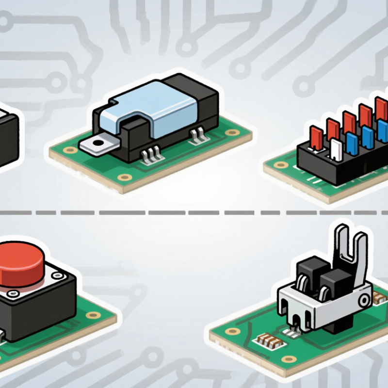
Table of Contents [Hide]
What Defines a PCB Micro Switch and How Does It Work?
A PCB micro switch is a compact, mechanically operated switch mounted directly on a printed circuit board. Its small size does not define how it works; a spring mechanism does. Pressing the actuator moves an internal contact, opening or closing an electrical circuit. In snap-action designs, a spring quickly changes the contact position after the actuator reaches a set point. The movement can feel crisp, even when the required force is light. That is the basic action.
Common PCB-mounted types include subminiature snap-action switches, tactile switches, and sealed versions designed to resist dust or moisture. They are not interchangeable. A tactile switch usually gives feedback when pressed, while a snap-action micro switch is selected for its switching behavior and operating force. Check the circuit rating, actuator travel, mounting pattern, and expected number of operations before choosing one. A mismatch can cause unreliable switching or premature wear.
Small details matter. A fraction of a millimeter in actuator travel may change whether a plastic button reliably reaches the switch. Board flex can also affect the feel, though it is easy to overlook during a quick bench test. Evaluate the switch in its actual enclosure, not only on an exposed board.