-
PRODUCTS & SERVICESOptimized cooling solutions for modern data centersProducts & ServicesOptimized cooling solutions for modern data centers
-
CAPABILITIESAdvancing liquid cooling technologiesCapabilitiesAdvancing liquid cooling technologies
-
TechnologiesLiquid Cooling InnovationTechnologiesLiquid Cooling Innovation
-
RESOURCESLatest News & InformationResourcesLatest News & Information
-
ABOUTOur history, leadership and ownershipAboutOur history, leadership and ownership
-
CONTACTFacility locations and global operational footprint







What Is a Metal Sanding Machine and How Does It Work?
A Metal Sanding Machine is more than a motorized abrasive tool. It is a controlled system for removing scratches, scale, burrs, and uneven surfaces from metal. Its abrasive belt, disc, or wheel moves across the workpiece at a regulated speed. Pressure and contact time determine how much material disappears. The result can be a smooth finish, a uniform grain, or a surface prepared for coating and welding.
Dr. Ioan D. Marinescu, a widely cited researcher in grinding and abrasive processes, explains the core idea clearly: “Abrasive machining is controlled cutting, not merely rubbing.” That principle helps readers understand the machine’s action. Tiny abrasive grains cut metal fragments from the surface. They also generate heat, dust, vibration, and sometimes visible discoloration. These details matter. A machine may look simple, yet poor belt selection can leave deep lines or uneven edges. Excessive pressure can overheat thin stainless steel. The operator’s judgment remains important.
This guide examines the main components of a Metal Sanding Machine, including its drive motor, abrasive media, contact wheel, work table, and dust-control system. It also explains how the machine transfers force through the abrasive surface. Real workshop conditions are rarely perfect. Belts wear out. Metal thickness changes. Even experienced operators make mistakes. Understanding these limitations leads to safer settings and more consistent results. A clean finish begins with control, not speed alone.
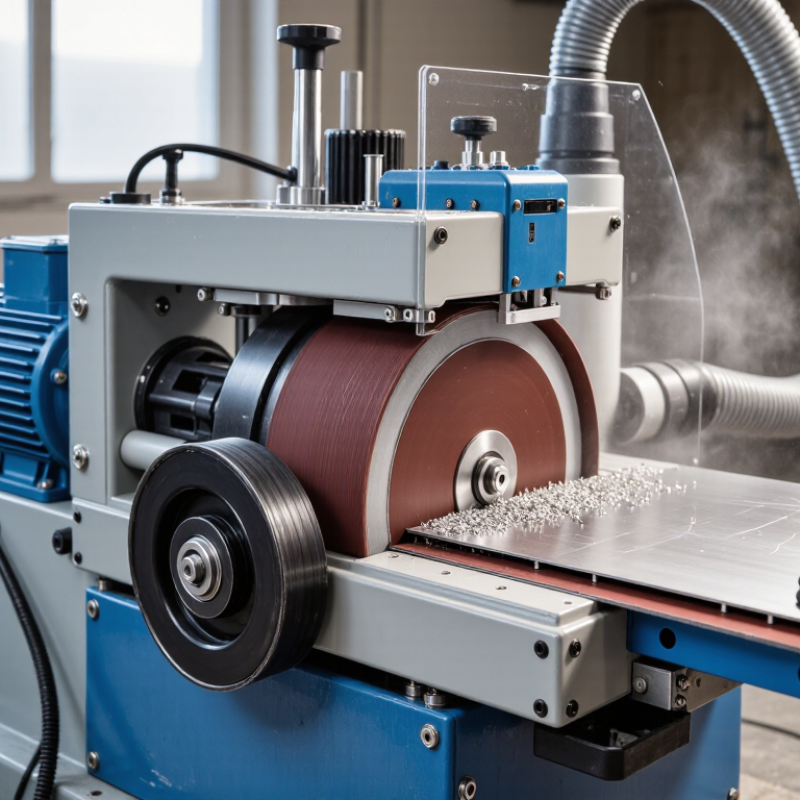
Table of Contents [Hide]
What Is a Metal Sanding Machine?
What Is a Metal Sanding Machine?
A metal sanding machine is industrial equipment that removes burrs, rust, weld marks, and sharp edges from metal surfaces. It uses an abrasive belt, disc, drum, or brush instead of a cutting blade. The workpiece moves against the abrasive surface, while controlled friction gradually removes unwanted material. Operators can adjust belt speed, contact pressure, and feed rate for different metals.
Some machines process flat sheets. Others handle tubes, profiles, or welded frames. A wide-belt model can smooth a steel panel in one pass, leaving visible parallel finishing lines.
A smaller disc unit offers better control around corners and narrow edges. In practice, surface preparation is rarely perfectly uniform. Excess pressure may create grooves, heat discoloration, or premature abrasive wear.
Safety and dust control are essential parts of the machine’s design. OSHA sets the permissible exposure limit for respirable crystalline silica at 50 micrograms per cubic meter over an eight-hour shift, where silica-containing materials are involved. OSHA’s noise standard also uses an 85-decibel action level and a 90-decibel eight-hour permissible exposure limit. These figures explain why local extraction, hearing protection, guarding, and routine inspection matter.
According to industry abrasive-market reports, demand is closely linked to automotive, fabrication, construction, and machinery production. Yet productivity alone can mislead. A faster belt is not always better. Material hardness, abrasive grain, cooling, and operator experience must be matched carefully. Sometimes, a slower pass produces the more reliable finish.