-
PRODUCTS & SERVICESOptimized cooling solutions for modern data centersProducts & ServicesOptimized cooling solutions for modern data centers
-
CAPABILITIESAdvancing liquid cooling technologiesCapabilitiesAdvancing liquid cooling technologies
-
TechnologiesLiquid Cooling InnovationTechnologiesLiquid Cooling Innovation
-
RESOURCESLatest News & InformationResourcesLatest News & Information
-
ABOUTOur history, leadership and ownershipAboutOur history, leadership and ownership
-
CONTACTFacility locations and global operational footprint







Why Choose a 125amp MCCB for Global Electrical Safety?
Choosing a 125amp Mccb can strengthen protection in commercial panels, industrial feeders, and demanding distribution systems. Its rated current supports circuits that exceed smaller breaker capacities without immediately requiring a larger frame. However, safe selection depends on more than the number printed on the label.
A properly specified 125amp Mccb can interrupt excessive current before overheated conductors damage insulation, terminals, or nearby equipment. Its molded case also helps protect internal components from dust, accidental contact, and mechanical stress. In practical installations, engineers examine cable ampacity, ambient temperature, prospective short-circuit current, and coordination with upstream devices. They may also review adjustable trip settings, making sure overload and instantaneous protection match the system design.
Small details matter.
International projects often reference IEC 60947-2, while local regulations and inspection practices may add further requirements. Qualified professionals should verify the breaker’s interrupting capacity, voltage rating, pole configuration, terminal arrangement, and certification documents. A product suitable for a 400-volt factory panel may not suit a different network or enclosure temperature. That assumption can be costly.
Field experience also shows that installation quality affects real protection. Loose lugs, undersized conductors, poor ventilation, and missing maintenance records can undermine a reliable breaker. Thermal scans and scheduled functional checks provide useful evidence, but they do not replace correct engineering. No device solves every risk.
This introduction examines why the 125amp Mccb remains relevant to global electrical safety, where it performs well, and where careful review is still necessary. Good engineering includes doubt.
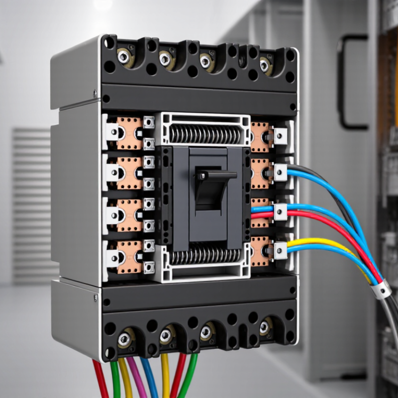
Table of Contents [Hide]
What Is a 125A MCCB and How Does It Work?
Why Choose a 125amp MCCB for Global Electrical Safety?
What Is a 125A MCCB and How Does It Work?
A 125A molded-case circuit breaker protects electrical circuits from excessive current. Its 125-amp rating indicates the maximum continuous current under specified conditions. It does not mean every installation should carry 125 amps continuously. Cable size, ambient temperature, enclosure ventilation, and load type still matter.
Inside the breaker, thermal protection responds to sustained overloads. A heated bimetal strip bends and releases the mechanism after a delay. Magnetic protection reacts much faster to short-circuit current. It trips the contacts open, limiting damage to cables, panels, and connected equipment. The interruption rating must match the prospective fault current at the installation point. That detail is easy to miss.
In practical panel inspections, technicians check terminal tightness, conductor condition, and signs of heat discoloration. They also verify that the breaker’s poles, trip settings, and accessories suit the system. A 125A MCCB may protect a motor feeder, distribution board, or commercial sub-circuit. However, motor starting currents can cause unwanted trips if settings are chosen casually. Coordination with upstream and downstream protective devices is essential. A clean calculation can still overlook real operating conditions. Residual-current protection may also be required, because an MCCB alone does not provide complete protection against electric shock. Selection should follow applicable electrical standards and be confirmed by a qualified professional.