-
PRODUCTS & SERVICESOptimized cooling solutions for modern data centersProducts & ServicesOptimized cooling solutions for modern data centers
-
CAPABILITIESAdvancing liquid cooling technologiesCapabilitiesAdvancing liquid cooling technologies
-
TechnologiesLiquid Cooling InnovationTechnologiesLiquid Cooling Innovation
-
RESOURCESLatest News & InformationResourcesLatest News & Information
-
ABOUTOur history, leadership and ownershipAboutOur history, leadership and ownership
-
CONTACTFacility locations and global operational footprint




Why Use a Concentric Reducer Fitting?
Why use a Concentric Reducer Fitting when a piping system changes diameter? The answer involves flow control, space, equipment protection, and installation accuracy. This fitting reduces pipe size along a shared centerline. Its symmetrical shape supports balanced flow in many vertical piping arrangements.
A concentric reducer can connect a larger pipe to a smaller one without creating an offset. That matters near pumps, valves, tanks, and compact process skids. The centered transition can simplify alignment and reduce unnecessary support adjustments. It may also help maintain a cleaner installation appearance. Small detail. Significant consequence.
W. Edwards Deming, a respected quality and process-improvement expert, said, “Quality comes not from inspection, but from the improvement of the production process.” His principle applies directly to reducer selection. Correct material, wall thickness, pressure rating, and dimensions should be confirmed before fabrication. Inspection cannot repair a poorly selected fitting.
Still, a Concentric Reducer Fitting is not always the perfect choice. Horizontal liquid lines may require an eccentric reducer to reduce air pockets or liquid accumulation. Engineers must review flow direction, phase conditions, welding requirements, and maintenance access. A rushed decision can produce vibration, drainage problems, or difficult field adjustments. That risk deserves attention.
This guide examines why concentric reducers remain widely used. It also considers their limitations. Practical selection depends on drawings, operating conditions, applicable standards, and the experience of qualified piping professionals. When those details align, the fitting becomes more than a simple transition. It becomes a controlled connection within the entire system.
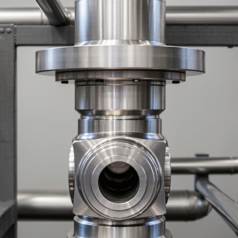
Table of Contents [Hide]
What Is a Concentric Reducer Fitting?
Why Use a Concentric Reducer Fitting?
A concentric reducer fitting connects pipes with different diameters along one shared centerline. Its ends align evenly around the central axis. This design creates a smooth, symmetrical transition between large and small pipes.
Concentric reducers are commonly used in vertical piping, process lines, and systems where balanced flow matters. They can reduce turbulence and support a compact installation. In practical work, fit-up becomes easier when the reducer matches the pipe outside diameters and wall schedules. Pressure rating, material compatibility, temperature, and connection type also require careful checking. A reducer may look simple, but a small mismatch can create welding gaps or installation stress. The most attractive layout is not always the safest one.
Tips: Confirm the pipe schedule before ordering. Check flow direction and installation orientation. In horizontal suction lines, poor positioning can trap air or affect pump performance. A field measurement is often more reliable than an old drawing. Leave enough clearance for welding, inspection, and future maintenance. Even experienced installers can overlook support requirements near a diameter change.